
Unlock Precision with Helical Interpolation in CNC Milling

TL;DR
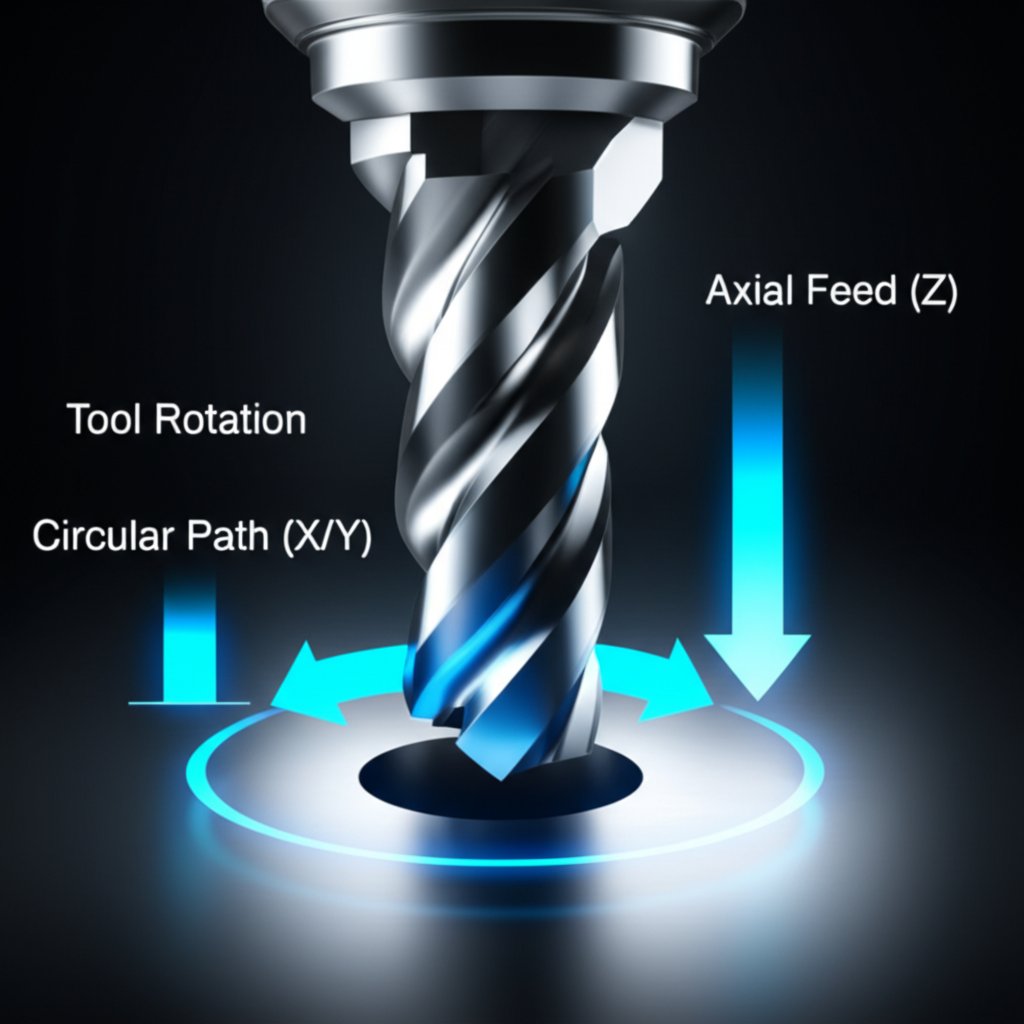
Helical interpolation is a CNC milling technique that creates or enlarges holes using a spiral toolpath. It requires simultaneous three-axis control (X, Y, and Z) to move the cutting tool in a helix. This method offers a flexible, smooth, and reliable alternative to traditional drilling, especially for large-diameter holes, circular pockets, and thread milling.
What Is Helical Interpolation and How Does It Work?
Helical interpolation, also known as circular ramping, is an advanced milling process where a cutting tool moves in a helical path to machine a hole. Unlike standard drilling, which plunges straight down, helical interpolation involves the coordinated, simultaneous movement of all three machine axes: a circular path in the X and Y planes combined with a steady axial feed in the Z plane. Imagine the tool descending a spiral staircase—that's the essence of the toolpath.
This technique requires a CNC machine with three-axis control capability. The process starts with the cutter orbiting and gradually feeding downwards at a specific pitch or ramp angle. This spiral motion allows a tool with a smaller diameter than the hole to progressively remove material. According to experts at Sandvik Coromant, this method is a much smoother process than linear ramping because it reduces the radial cut, enables pure down-milling, and provides superior chip evacuation.
A key distinction is its difference from linear ramping. While both are methods for entering a workpiece without drilling a pilot hole, linear ramping involves moving the tool in a straight line on two axes (e.g., X and Z). Helical interpolation, however, engages all three axes to create its circular, descending path. This distribution of cutting forces across three axes, rather than two, often results in longer tool life and a better surface finish.
The outcome of a successful helical interpolation operation is a clean, precise hole. Because the tool is smaller than the final diameter, there is ample space for chips to be evacuated, which is critical for preventing chip recutting and tool failure. This makes it an exceptionally reliable process, especially in difficult-to-machine materials where chip control is paramount.
Key Applications and Advantages of Helical Interpolation
Helical interpolation is a versatile technique prized in job shop environments and production settings for its flexibility and efficiency. Its primary applications include creating large-diameter holes, opening up existing holes, milling circular pockets, and performing thread milling operations. The main advantage is that a single end mill can produce a wide range of hole sizes, significantly reducing the need for a large inventory of different-sized drills and minimizing tool change time.
The process offers substantial benefits over traditional drilling, especially for large holes. Manufacturing a large-diameter hole with a drill can require immense horsepower and machine rigidity. Helical interpolation, by contrast, uses a smaller tool and takes lighter radial cuts, placing less stress on the machine spindle and frame. This makes it possible to create large holes on machines that might otherwise lack the power for heavy drilling operations. As noted by industry specialists, it's a very fast and economical process compared to purchasing multiple large indexable drills.
For businesses looking to leverage advanced techniques like helical interpolation in their product development, services like XTJ's formative manufacturing offer expert DFM feedback and rapid prototyping across a wide range of materials. Partnering with such services can help optimize designs for efficient and high-quality production from the outset.
To summarize, the choice to use helical interpolation often comes down to a balance of efficiency, cost, and machine capability. Here is a breakdown of its primary pros and cons:
Pros
- Tool Flexibility: One tool can create holes of various diameters, reducing tool inventory and costs.
- Reduced Cutting Forces: The gradual spiral engagement is smoother and puts less stress on the machine and tool than drilling.
- Excellent Chip Evacuation: The space between the tool and the hole wall allows chips to be cleared effectively, which is crucial for deep holes and gummy materials.
- Superior Surface Finish: The milling action often produces a better wall finish than a drill bit.
- Versatility: It is effective for creating holes from solid material, enlarging existing holes, and thread milling.
Cons
- Machine Requirement: It requires a CNC machine capable of simultaneous three-axis movement.
- Slower Cycle Time for Small Holes: For small, standard-sized holes, a traditional drilling operation is often faster and more productive.
- Programming Complexity: While CAM software simplifies it, manual programming requires careful calculation of the helical path.
Programming Helical Interpolation: G-Code and Calculations
Programming helical interpolation involves using circular interpolation G-codes (G02 for clockwise and G03 for counter-clockwise) with the addition of a Z-axis coordinate to define the depth change for each circular move. This combination instructs the CNC controller to generate the required spiral toolpath. While most modern CAM systems can generate this code automatically, understanding the manual process is valuable for machinists and programmers.
A typical line of G-code for a single 360-degree helical move might look like this: G03 X[end_x] Y[end_y] I[arc_center_x] J[arc_center_y] Z[end_z] F[feed_rate];. In this command, I and J define the arc's center relative to the start point, while the Z value specifies the axial depth to descend during that circular movement. Alternatively, some controllers use R to define the arc's radius. As explained by CNCCookbook, it's often more reliable to break a full circle into four 90-degree arcs to avoid issues with how different controllers interpret the commands.
Here is a simplified G-code example for milling a 1-inch diameter hole to a depth of 0.25 inches using a 0.5-inch end mill, starting from the hole center (X0, Y0):
G00 G90 G54 X0 Y0;     (Move to hole center)
G43 H1 Z0.1;           (Tool length comp, move above part)
G01 Z0 F50.0;          (Feed to part surface)
G01 G41 D1 X0.25 Y0;   (Cutter comp on, move to start of arc)
G03 X0.25 Y0 I-0.25 J0 Z-0.125 F20.0; (First 360-degree helical pass)
G03 X0.25 Y0 I-0.25 J0 Z-0.25;      (Second 360-degree helical pass)
G01 G40 X0 Y0;         (Cutter comp off, return to center)
G00 Z1.0;              (Retract tool)
Creating a program from scratch involves a few key steps:
- Select the Right Tool: The tool diameter must be chosen carefully. It must be small enough to allow for chip evacuation but large enough for rigidity. A common rule of thumb is that the tool diameter should not exceed 70% of the final hole diameter.
- Calculate the Pitch: The pitch is the vertical distance the tool descends in one full 360-degree revolution. This is determined by the ramp angle, which is typically a small value (e.g., 1-3 degrees for hard materials).
- Determine Feeds and Speeds: The feed rate must be adjusted for the helical path. The programmed feed rate is for the tool's center, but the cutting edge on the circumference travels a longer distance. CAM software and specialized calculators can help determine the correct feed rate to maintain the desired chip load.
- Write the G-Code: Using G02 or G03, program the circular path with incremental Z-axis movements for each revolution until the final depth is reached.
Frequently Asked Questions
1. What is helical interpolation?
Helical interpolation is a CNC milling process that creates or enlarges holes by moving a cutting tool along a spiral path. It involves the simultaneous, coordinated movement of the machine's X, Y, and Z axes to generate the helix, providing a flexible alternative to drilling.
2. What is the G code for helical interpolation?
The G-code for helical interpolation uses the standard circular interpolation commands, G02 (clockwise) or G03 (counter-clockwise), with the addition of a Z-axis coordinate in the same block. For example, G03 I... J... Z...; commands the tool to move in a counter-clockwise arc while simultaneously moving downward in the Z-axis.
3. What is the difference between helical interpolation and ramping?
The primary difference is the toolpath's shape. Helical interpolation (or circular ramping) involves moving the cutter in a circular or helical motion, engaging all three axes (X, Y, Z). Linear ramping, by contrast, moves the cutter in a straight line while descending, engaging only two axes at a time (e.g., X and Z or Y and Z).
4. What are the methods of interpolation in CNC?
The most common methods of interpolation in CNC machining are linear interpolation (G01), which moves the tool in a straight line between two points, and circular interpolation (G02, G03), which moves the tool along a circular arc. Helical interpolation is an advanced form of circular interpolation that adds a simultaneous linear movement on a third axis.
-
Posted in
CNC milling, G-Code, helical interpolation, Machining, thread milling


