How to Avoid Thin Wall Defects in CNC Machining
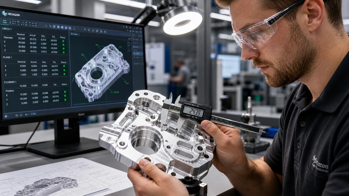
Focus Keyword: thin wall CNC machining Secondary Keywords: cnc thin wall deformation, thin wall aluminum machining, prevent chatter marks in cnc milling Slug: how-to-avoid-thin-wall-defects-in-cnc-machining Image ALT: Thin wall CNC machining deformation prevention diagram
Meta Title: How to Avoid Thin Wall Defects in CNC Machining Meta Description: Learn common thin-wall CNC machining defects, root causes, design guidelines and proven machining strategies to reduce chatter, deformation and dimensional errors for aluminum precision parts.
Introduction
Thin-wall machined components are widely used in aerospace, automotive, electronics, medical devices and industrial automation systems. Engineers specify thin-wall geometries to cut overall weight while preserving required structural performance, a key requirement for lightweight and compact hardware assemblies.
Even so, thin-wall CNC machining brings unique manufacturing challenges. Low rigidity of thin sections makes parts susceptible to deflection from cutting forces, thermal expansion, and residual stress redistribution. These issues often result in wall deformation, inconsistent thickness, chatter marks, poor surface finish, or out-of-tolerance dimensions.
For mechanical engineers, product designers and sourcing managers, mastering thin-wall machining best practices helps stabilize quality and control production costs. This handbook covers typical thin-wall defects, root causes, process solutions, design rules and QC methods to minimize distortion during CNC production. If you need reliable support for complex lightweight parts, you can work with suppliers offering custom thin-wall CNC machining services for prototype and low-volume production.
1. What Is Thin Wall CNC Machining?
Thin-wall CNC machining describes the fabrication of components where wall thickness is small relative to the part’s overall size. Manufacturers typically produce these parts with CNC milling, turning and multi-axis machining. Aluminum alloys are the dominant material choice, thanks to their excellent strength-to-weight ratio and good machinability.
Common applications:
- Lightweight aerospace brackets and structural frames
- Aluminum electronic enclosures and housings
- Automotive heat sinks and mounting brackets
- Protective mechanical covers and instrument shells
- Precision automation fixtures
The core challenge is low structural stiffness. Under cutting pressure, thin walls deflect or vibrate, making it difficult to maintain stable geometry. Consistent results depend on thoughtful part design, rigid workholding, proper cutting tool selection and structured inspection procedures.

2. Common Defects in Thin Wall CNC Machining
2.1 Wall Deformation
Cutting forces push thin walls away from the cutting path. Once the cutting load is removed, partial springback occurs, creating dimensional differences between the machined state and final inspection.
2.2 Vibration & Chatter Marks
Thin sections lack rigidity. Overly aggressive tool engagement, weak fixturing or mismatched spindle speeds trigger vibration, leaving visible chatter marks that hurt surface quality and dimensional accuracy.
2.3 Uneven Wall Thickness
Uneven thickness comes from material deflection, flawed toolpaths, heavy cutting passes or accumulated setup errors. This defect compromises consistent mechanical strength and assembly reliability for high-precision parts.
2.4 Distortion from Residual Stress
Material removal redistributes internal stress locked inside the workpiece. Asymmetric pocketing or heavy stock removal from one side frequently causes aluminum thin-wall parts to warp after unclamping.
3. Root Causes of Thin-Wall Distortion
- Cutting forces: Excessive radial engagement or aggressive feed rates bend thin sections
- Cutting heat: Local thermal expansion shifts dimensions without proper cooling control
- Poor workholding: Over-clamping or insufficient support introduces pre-machining deformation
- Tool deflection: Long, low-rigidity cutters bend under cutting load
- Material residual stress: Internal stress releases as stock is removed
- Unbalanced machining sequence: Removing too much material from one side early in the process
Fixing distortion requires both design optimization and process control, rather than only adjusting cutting parameters.

4. Practical Machining Strategies to Prevent Defects
4.1 Adopt Multiple Light Cutting Passes
Avoid finishing the final wall thickness in one heavy cut. Rough out most stock and leave a uniform finishing allowance, then use semi-finishing and finishing passes gradually. Light cuts greatly reduce cutting load and deflection.
4.2 Optimize Cutting Parameters
For aluminum thin-wall parts:
- Reduce radial tool engagement
- Match feed rate to your tool and alloy
- Use sharp cutting tools optimized for aluminum
- Eliminate unnecessary tool dwell time
- Keep stable cutting conditions and monitor vibration
All parameters should be tuned for alloy grade, wall height, tool overhang and machine rigidity.
4.3 Optimize Workholding & Fixture Support
Fixtures must secure the part firmly without excessive clamping pressure. Common solutions include custom fixtures, auxiliary support points, soft jaws and temporary support structures. Vacuum chucks work well for some ultra-thin delicate workpieces.
4.4 Use Balanced Machining Sequences
Machine opposite walls alternately and process symmetrical features in stages. A standard workflow: roughing → stress relief (where applicable) → final finishing, which balances stress release.
5. Design Guidelines for Thin-Wall CNC Parts
Design choices can reduce manufacturing risk before machining starts:
- Do not specify unnecessarily thin walls. Set thickness based on load, part size and machining capability.
- Keep wall thickness consistent wherever possible to maintain uniform rigidity.
- Add reinforcing ribs to boost stiffness without major weight gain, ideal for large housings and covers.
- Limit deep pockets surrounded by thin walls. Optimize corner radii and pocket depth for easier tool access.
- Check tool accessibility, avoid long tool overhang that triggers vibration.
These rules lower machining difficulty and cut unnecessary prototype cost.
6. Inspection & Post-Processing Notes
Standard inspection items:
- CMM measurement for critical dimensions and GD&T callouts
- Precision thickness checking for thin sections
- Surface roughness testing
- Visual inspection for chatter marks
- Dimensional check after releasing clamps to capture springback
Post-finishing requires extra care. Anodizing, polishing and deburring may alter thin-wall dimensions. Heavy polishing removes extra material; clamping during finishing can bend delicate features. Define finishing allowances at the drawing stage for tight tolerance parts.
7. Sourcing Tips for Buyers & Engineering Teams
- Submit complete 3D CAD files and 2D drawings, mark wall thickness, critical tolerances and GD&T requirements.
- Highlight critical surfaces that require strict thickness control or surface finish.
- Discuss machining strategy with your supplier: fixturing plan, cutting sequence and stress control.
- Confirm material grade and temper condition.
- Clarify inspection requirements: FAIR, CMM reports or batch sampling.
- Validate prototypes before full production to identify deformation risks early.
FAQ
- What is the minimum wall thickness for CNC machined aluminum? There is no universal standard. Generally, 0.8–1.0 mm is achievable under ideal conditions. Walls thinner than this become unstable and much more costly. The practical limit depends on wall height, unsupported span, alloy, fixturing and tolerance requirements. Always confirm with your supplier during design review.
- What causes thin wall deformation during CNC machining? The main drivers are cutting force, insufficient support, cutting heat, tool chatter, clamping stress and residual stress release. Multi-pass light cuts, rigid fixtures and balanced machining sequences help mitigate distortion.
- Can surface finishing damage thin-wall features? Yes. Aggressive polishing, heavy deburring and improper anodizing handling can alter wall thickness or bend thin geometry. Leave proper finishing stock and add final inspection after surface treatment.
Final Thoughts
Thin-wall CNC machining requires close coordination between design, material selection, machining process and quality control. Defects such as deformation and chatter come from low part rigidity, cutting loads and residual stress.
Engineers can avoid most issues by following manufacturability rules: reasonable wall thickness, reinforcing ribs, stable fixturing and balanced cutting sequences. Early communication with an experienced CNC supplier helps turn lightweight thin-wall designs into consistent, qualified production parts.