
Essential CNC File Formats Explained: A Guide to CAD and CAM Files

TL;DR
CNC (Computer Numerical Control) machining relies on specific digital files to translate a design into machine instructions. These files fall into three main categories: 2D vector files like DXF and SVG for cutting flat profiles and engravings; 3D model files such as STEP and STL for creating complex, three-dimensional parts; and machine instruction files, known as G-code, which provide the final commands that guide the machine's movements.
The Crucial Link Between Design and Machine: Why CNC File Formats Matter
Understanding common CNC file formats is essential because they are the bridge between a digital idea and a physical object. The entire manufacturing process hinges on successfully translating a design from a Computer-Aided Design (CAD) program into instructions for a Computer-Aided Manufacturing (CAM) system, which then directs the CNC machine. This workflow ensures that the machine cuts, carves, or prints the part exactly as envisioned. Without the correct file format, this translation can fail, leading to costly errors, wasted material, and significant delays.
In this process, files generally fall into two categories: native files and exchange files. Native files are specific to the software they were created in (like a .SLDPRT file from SolidWorks) and contain all the design logic and history, making them easy to edit within that program. Exchange files, like STEP or DXF, are standardized formats designed for interoperability, allowing designs to be shared and used across different software platforms. While they don't retain the original design history, they accurately represent the part's geometry, which is crucial for manufacturing.
The journey from concept to creation typically follows three stages. First, the part is designed in CAD software. Next, the design file is imported into CAM software, where a machinist defines the toolpaths—the exact route the cutting tool will take. Finally, the CAM software uses a machine-specific 'post-processor' to generate the G-code, which is the set of instructions the CNC controller executes. Sending a manufacturer a high-quality design file is paramount, as they will almost always generate their own G-code to match their specific machines and tooling.
Here is a simplified breakdown of the workflow:
| Stage | Primary Task | Typical File Types |
|---|---|---|
| CAD (Design) | Create the 2D or 3D geometry of the part. | DXF, SVG (2D); STEP, STL (3D) |
| CAM (Toolpath Generation) | Import the design and generate cutting strategies. | Imports design files, outputs G-code. |
| Controller (Machine Execution) | Read and execute the instructions. | G-code (.NC, .TAP, .GCODE) |
2D Vector Formats for Outlines and Engraving: DXF and SVG
For projects involving cutting, profiling, or engraving on flat materials, 2D vector formats are the industry standard. Unlike pixel-based raster images (like JPG or PNG), vector files use mathematical lines, curves, and points to define shapes. This allows them to be scaled to any size without losing resolution, ensuring perfectly crisp and accurate cuts. The two most prevalent 2D vector formats in CNC work are DXF and SVG.
DXF (Drawing Exchange Format) was developed by Autodesk as a universal format for sharing 2D designs between different CAD programs. Its long history and open specification have made it a workhorse in the engineering and fabrication worlds. It is ideal for precise outlines for signs, mechanical brackets, and decorative inlays. SVG (Scalable Vector Graphics), on the other hand, originated in web design. It's a lightweight, open-standard format that excels at handling logos, text, and other artwork, making it popular among hobbyists and for laser cutting applications.
While both are effective, they have distinct strengths and weaknesses. DXF offers near-universal support in professional CAM software but can sometimes have issues with units or scaling when moved between programs. SVG is excellent for its small file sizes and ease of use with design software like Adobe Illustrator or Inkscape, but complex effects like gradients or strokes may not translate correctly into toolpaths unless they are first converted to simple outlines.
To ensure a successful project when using 2D vector files, consider these practical tips:
- Ensure Consistent Units: Always verify that your design file (e.g., in millimeters) matches the units expected by your CAM software to avoid incorrect scaling.
- Convert Text to Paths: Fonts are not geometry. Convert all text elements into vector paths or outlines to ensure the machine can read and cut the letter shapes correctly.
- Close Open Loops: For profile cutting, ensure all your vector shapes are closed loops. An unclosed shape can prevent the CAM software from generating a complete toolpath.
- Simplify Your Design: Remove any unnecessary fills, strokes, or layers that are not part of the final cutting instructions. This creates a cleaner file that is easier for the CAM software to process.
3D Model Formats for Complex Shapes: STEP, STL, and IGES
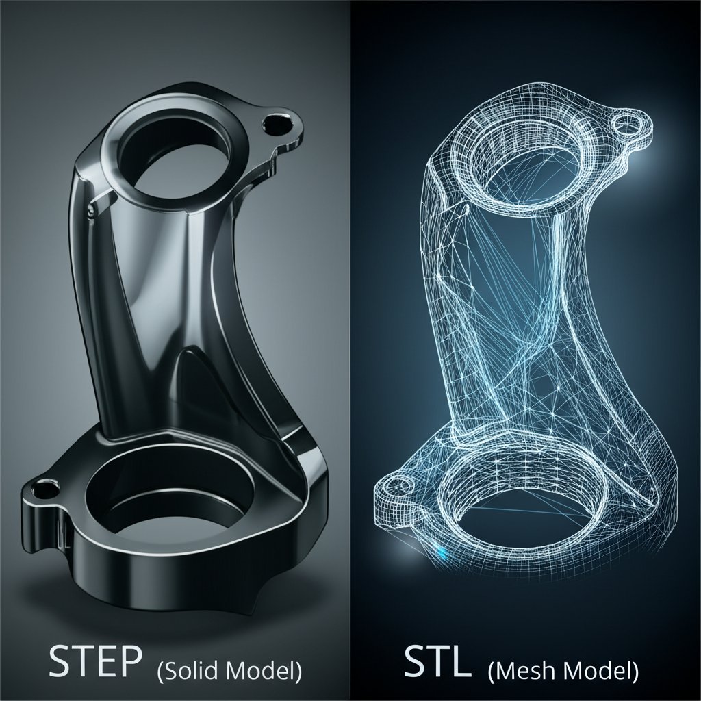
When manufacturing parts with complex curves, contours, and three-dimensional features, 2D files are insufficient. This is where 3D model formats become essential. The most common formats in CNC machining are STEP, STL, and the older IGES. Understanding the fundamental difference between them is crucial, as choosing the wrong one can compromise the accuracy of your final part. The primary distinction lies in how they represent geometry: solid models versus mesh models.
STEP (Standard for the Exchange of Product Data) and IGES (Initial Graphics Exchange Specification) are solid model formats. They define the part using pure mathematical representations of its surfaces and solids. This makes them extremely precise and is why STEP is widely regarded as the industry standard for professional CNC machining. It's a neutral format, meaning it can be used across virtually any CAD/CAM platform. In contrast, STL (Stereolithography) is a mesh format. It approximates the surface of a 3D model by covering it in a network of small, flat triangles, a process called tessellation. While this is perfect for 3D printing, it is an approximation and lacks the pure geometric data needed for high-precision machining.
Because STL files are just a surface mesh, they are generally unsuitable for CNC machining, as the CAM software cannot interpret the triangulated geometry to create accurate toolpaths. Attempting to convert an STL back to a solid format like STEP is a complex and often error-prone process that rarely yields a perfect result. For any project requiring precision, such as mechanical components or functional prototypes, providing a STEP file is the best practice. When seeking professional manufacturing, partners like XTJ's formative manufacturing services rely on high-quality STEP files to ensure the production of accurate, functional parts with excellent surface finishes, backed by expert DFM feedback.
Here is a comparison of the key 3D formats:
| Criteria | STEP (.step, .stp) | STL (.stl) | IGES (.igs, .iges) |
|---|---|---|---|
| Precision | Very High (Mathematical Solid) | Low to High (Approximated Mesh) | High (Mathematical Solid) |
| Best Use Case | Precision CNC Machining, Engineering | 3D Printing, 3D Relief Carving | Legacy Data Exchange |
| Editability | High (in CAD software) | Difficult (mesh editing) | Moderate |
| Industry Standard | Yes, the modern standard | No (for CNC machining) | Largely superseded by STEP |
The Final Command: Understanding G-Code (.NC, .TAP)
After a design has been created in CAD and toolpaths have been programmed in CAM, one final file type is generated: G-code. This is not a design file but rather the fundamental programming language that directly controls the CNC machine. Often saved with extensions like .NC, .TAP, or .GCODE, it is a plain text file containing a sequential list of commands that tell the machine exactly where to move, how fast to go, and when to turn the spindle on or off.
G-code is generated by the CAM software through a component called a post-processor. The post-processor is critical because it tailors the G-code to the specific dialect and capabilities of a particular CNC machine controller. A G-code file written for one machine will likely not work on another, as different controllers may use slightly different commands or syntax. This is why manufacturing shops will always generate their own G-code from the design file you provide; they need to ensure it is optimized for their specific equipment, tooling, and processes.
To a novice, a G-code file can look intimidating, but its structure is logical. Each line represents a command, typically starting with a letter followed by numerical values that define parameters like coordinates or speed.
Here is a simple, annotated example:
G00 Z5; Rapid move up to a safe height of Z=5mm
G01 X10 Y20 F150; Linear move to coordinates X=10, Y=20 at a feed rate of 150 mm/min
M03 S12000; Turn the spindle on clockwise at 12000 RPM
For hobbyists running their own machines, it's a vital safety practice to run an 'air-cut'—running the G-code program with the tool high above the material—to visually verify that the toolpaths are correct and there are no unexpected movements before cutting the actual workpiece. However, when working with a professional service, your responsibility ends with providing a high-quality design file like a STEP or DXF. The experts will handle the complex task of generating perfect, machine-specific G-code.
Frequently Asked Questions About CNC Files
1. What type of file do I need for CNC?
The best file type depends on your project. For 2D cutting, profiling, or engraving, a vector file like DXF is the most common and reliable choice. For 3D projects that require precision machining of complex shapes, a solid model file like STEP is the industry standard and highly preferred by manufacturers.
2. Do CNC machines use SVG files?
Yes, many CNC machines, especially those used by hobbyists and for laser cutting or routing, can use SVG files. SVG is a vector format that works well for 2D shapes, logos, and text. However, for best results, you should ensure the SVG contains only simple paths and that any text or complex strokes have been converted to outlines before sending it to the CAM software.
-
Posted in
CAD, CAM, CNC, file formats, G-Code


