
Essential DFM Tips for Cost-Effective CNC Milled Part Manufacturing

TL;DR
Design for Manufacturing (DFM) for CNC milled parts is a crucial practice for creating components efficiently and cost-effectively. The core idea is to simplify part geometry to minimize machining time and expense. Key strategies include using generous internal corner radii, avoiding deep and narrow pockets, standardizing features like holes and threads, and only specifying tight tolerances when absolutely necessary.
Understanding the Core Principles of DFM for CNC
Before diving into specific design tips, it’s essential to understand the philosophy behind Design for Manufacturing (DFM) and what drives costs in CNC machining. DFM is an engineering approach that prioritizes ease of manufacturing from the very first design sketch. By considering the manufacturing process, materials, and testing early on, you can significantly reduce production time, cut costs, and improve the final quality of your parts. This proactive approach helps prevent costly redesigns and production delays down the line.
The primary cost drivers in CNC machining can be broken down into several key areas. First are the non-recurring engineering (NRE) costs, which include the time spent planning the job and programming the machine's toolpaths. Complex designs require more programming time, increasing this initial expense. Another factor is setup time—the manual labor required to load tools, install fixtures, and calibrate the machine for a new part. Minimizing the number of unique setups is a cornerstone of effective DFM.
Once production begins, costs scale with material volume, machining time, and tooling wear. Machining time is directly influenced by part geometry; simpler designs that can be cut with larger, stiffer tools allow for a higher material removal rate (MRR), making the process faster and cheaper. Conversely, complex surfaces or tiny features require smaller tools and slower speeds, dramatically increasing machine time. Getting early DFM feedback from an expert team can be invaluable. For instance, services like XTJ's comprehensive formative manufacturing provide critical engineering input to optimize designs before production, ensuring a smoother path from concept to high-quality prototype.
Finally, tolerances and inspection requirements have a non-linear impact on cost. While standard tolerances are relatively easy to achieve, tightening them requires more precise process control, specialized tools, and often slower machining speeds. As detailed by manufacturing experts at Five Flute, the cost can increase exponentially as tolerances become tighter. Therefore, a fundamental principle of DFM is to apply tight tolerances only to critical functional interfaces, saving significant cost on non-critical features.
Critical DFM Guidelines for Part Geometry and Features
Optimizing the geometry of a part is at the heart of DFM for CNC milling. By following established guidelines for common features, you can avoid common pitfalls that inflate costs and complexity. These rules of thumb are based on the physical limitations of cutting tools and machine capabilities.
Pockets and Cavities
Deep and narrow pockets are a frequent source of increased machining time and risk. The challenge lies in tool deflection and chip evacuation. A long, thin cutting tool is more likely to vibrate or break, resulting in poor surface finish and dimensional inaccuracy. A widely accepted guideline, recommended by sources like Protolabs Network (formerly Hubs), is to limit the depth of a pocket to no more than four times its width. Machining pockets deeper than six times the tool diameter is considered deep milling and requires specialized tooling and techniques, which adds to the cost.
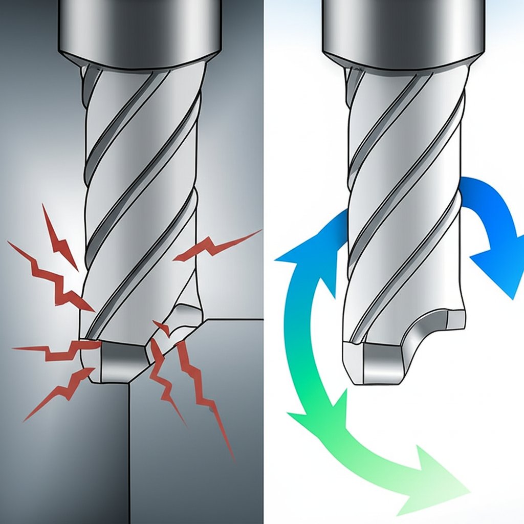
Internal Corners and Radii
CNC end mills are cylindrical, meaning they cannot create perfectly sharp internal corners. Every internal corner will have a radius corresponding to the tool used to cut it. Attempting to create a near-sharp corner requires a very small diameter tool, which is fragile and slow. A best practice is to design internal corner radii to be at least one-third of the cavity's depth. Making the radius slightly larger than the tool's radius allows for a smoother cutting path, reducing tool wear and improving surface finish.
Wall Thickness
Thin walls present a major challenge in CNC machining. For metals, thin walls are prone to vibration (chatter), which degrades surface finish and accuracy. For plastics, thin walls can warp due to heat generated during machining or from residual stresses in the material. A safe minimum wall thickness is generally 0.8 mm for metals and 1.5 mm for plastics. Anything thinner should be carefully evaluated and is often highlighted as a risk in manufacturability analysis.
To illustrate these concepts, consider the following design optimizations:
| Feature | Problematic Design | DFM-Optimized Design |
|---|---|---|
| Internal Corners | Sharp, 90-degree internal corners specified in the CAD model. | Generous corner radii added (e.g., radius of 3mm or more), allowing a larger, more stable tool to be used. |
| Pockets | A deep, narrow pocket with a depth-to-width ratio of 8:1. | Pocket depth reduced or width increased to achieve a ratio of 4:1 or less, enabling standard tooling and faster machining. |
| Thin Walls | A 0.5mm thick wall in an aluminum part. | Wall thickness increased to at least 0.8mm to prevent vibration and potential deformation during machining. |
Advanced Considerations: Threads, Text, and Tolerances
Beyond basic geometry, several other features can significantly impact the manufacturability and cost of a CNC milled part. Paying close attention to threads, text, and tolerances is crucial for avoiding unnecessary expenses and production hurdles.
Threads
When designing threaded holes, standardization is key. Using standard thread sizes ensures that common taps or thread mills can be used, avoiding the need for custom tooling. It is recommended to use thread sizes of M6 or larger when possible, as these can be created with more robust CNC threading tools, reducing the risk of tool breakage. For thread length, most of the holding strength comes from the first few turns. A thread length of 1.5 to 3 times the nominal diameter is typically sufficient; anything longer provides little additional benefit and increases machining time.
Text and Lettering
Adding text to a part should be done with machinability in mind. Engraved (recessed) text is always preferred over embossed (raised) text because it requires removing less material. For clarity and ease of machining, use a sans-serif font like Arial with a font size of at least 20 points. This ensures the features of the letters are wide enough for a cutting tool to create them cleanly. As noted by manufacturing service Protolabs, these simple choices help align the design with standard machine capabilities.
Tolerances
Tolerances define the acceptable dimensional variance of a feature and are one of the biggest hidden cost drivers. While CNC machines are highly precise, achieving extremely tight tolerances is a slow and expensive process. The default machining tolerance, often around ±0.13mm (±0.005 in.), is sufficient for most non-critical features. Specifying a tighter tolerance should be a deliberate decision reserved only for surfaces that are critical to the part's function, such as mating faces or bearing bores. Unnecessarily tight tolerances on non-functional features is a common and costly mistake.
Before finalizing your design, review it against this checklist:
- Tolerances: Are all specified tolerances functionally necessary? Have non-critical dimensions been left at the standard tolerance?
- Text: Is all text engraved, using a large, sans-serif font?
- Threads: Are thread sizes standard (M6 or larger preferred) and not excessively long?

A Smarter Approach to Production: Conclusion
Embracing Design for Manufacturing is not about limiting creativity; it's about channeling it into designs that are both functional and efficient to produce. By understanding the core principles of CNC machining—from cost drivers to the physical limitations of cutting tools—engineers and designers can make informed decisions that lead to significant savings in time and money. Simple adjustments to geometry, such as adding generous radii to internal corners, avoiding overly deep pockets, and standardizing features, can dramatically streamline the production process.
Furthermore, paying attention to advanced details like tolerances, text, and threads prevents unnecessary complexity and expense. The key takeaway is to design with intent, questioning the necessity of every feature and tolerance. This mindset, combined with the practical guidelines outlined here, transforms DFM from a checklist into a powerful tool for creating higher quality, cost-effective CNC milled parts.
Frequently Asked Questions
1. What is the most common DFM mistake in CNC machining?
One of the most common and costly mistakes is specifying unnecessarily tight tolerances on non-critical features. This dramatically increases machining time, inspection requirements, and the potential for scrapped parts without adding any functional value. Always question if a tight tolerance is essential for the part's performance.
2. Why are sharp internal corners a problem for CNC milling?
CNC milling uses rotating cylindrical tools (end mills) to remove material. Because the tool is round, it cannot create a perfectly sharp internal corner; it will always leave a radius. To create a very small radius, a very small diameter tool must be used, which is slow, fragile, and increases cost. Designing with a generous radius that accommodates a larger tool is far more efficient.
3. How much can DFM save on CNC machined parts?
The savings can be substantial, often ranging from 25% to 50% or more, depending on the initial complexity of the design. Simplifying a part to reduce the number of machine setups, switching from complex surfacing to 2D features, and loosening non-critical tolerances can all lead to significant reductions in both programming and machining time, which are the primary cost drivers.
-
Posted in
cnc machining, CNC milling, DFM, manufacturing, part design
