
Essential Strategies to Stop CNC Tool Chatter in Milling

TL;DR
To avoid tool chatter in CNC milling, you must take a systematic approach to increase the overall rigidity of your setup, optimize cutting parameters to move out of harmonic frequencies, and select the right cutting tool for the job. This involves shortening tool overhang, ensuring secure workholding, making small adjustments to spindle speed (RPM), maintaining proper chip load, and using modern end mills with variable helix or pitch geometries designed to suppress vibrations. A stable, rigid system is the foundation for a chatter-free operation.
Understanding the Root Causes of CNC Chatter
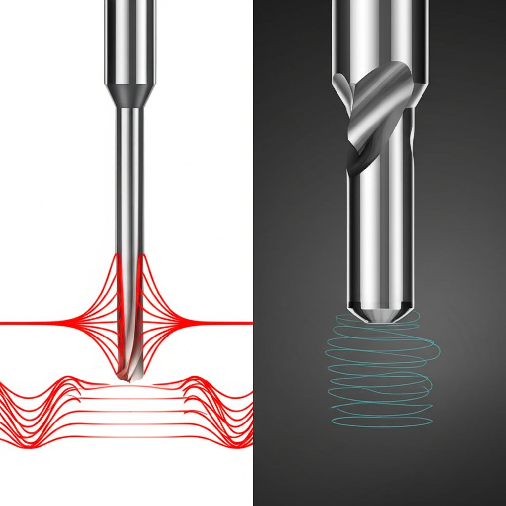
Tool chatter is a persistent and destructive issue in CNC machining, identified by the high-pitched squeal of the cutter and the wavy, imperfect surface finish it leaves behind. It's a form of self-excited vibration where the cutting forces cause the tool or workpiece to oscillate. This vibration becomes a problem when the frequency of the cutting action matches a natural or resonant frequency of the machining system, causing the vibrations to amplify dramatically. Think of it like pushing someone on a swing: if you push at just the right moment in their arc, they go much higher with little effort. Chatter is the same principle, but it leads to poor part quality, rapid tool wear, and potential damage to the machine's spindle.
Unlike forced vibration, which might come from an imbalanced machine component, chatter is self-perpetuating. The initial tiny vibration creates a wavy surface on the workpiece. On the next pass, the cutting edge hits this uneven surface, which causes the cutting force to fluctuate. This fluctuation then reinforces the vibration, creating a feedback loop that sustains and worsens the chatter. This resonance is why chatter can appear suddenly at certain spindle speeds or depths of cut and disappear with a small adjustment.
The economic impact of uncontrolled chatter is significant. It directly leads to scrapped parts that fail to meet surface finish or dimensional tolerance requirements. Furthermore, the intense vibrations accelerate the wear on cutting edges, leading to premature tool failure and increased tooling costs. In severe cases, sustained chatter can even cause long-term damage to expensive machine components like spindle bearings. Understanding that chatter is a system-wide stability problem—involving the machine, tool holder, tool, and workpiece—is the first step toward diagnosing and solving it effectively.
Before adjusting any parameters, a machinist should perform a quick diagnostic check to confirm if chatter is the root cause of the problem. Here are key indicators to look for:
- Audible Noise: A distinct high-pitched squeal or loud humming sound during the cut is the most common sign.
- Visual Patterns: Examine the machined surface for regular, wavy patterns or visible chatter marks. These indicate the tool was vibrating consistently as it moved across the part.
- Poor Tool Life: If cutting edges are chipping or wearing out much faster than expected for the material and parameters, vibration is a likely culprit.
- Inconsistent Finishes: The surface finish may be acceptable in some areas of the toolpath but poor in others, especially in corners or areas of deep engagement where forces are higher.
Maximizing System Rigidity: The First Line of Defense
The most fundamental principle in eliminating tool chatter is to maximize the rigidity of the entire machining system. A stiff, stable setup is less susceptible to the vibrations that initiate chatter. Rigidity isn't just about the machine tool itself; it encompasses every element from the spindle to the workpiece. This includes the tool holder, the cutting tool, and the workholding fixture. Addressing rigidity first often solves the problem without needing to compromise on aggressive cutting parameters.
Tool selection and setup are critical. The tool's length-to-diameter ratio is a major factor in its stiffness. A long, thin tool will deflect and vibrate much more easily than a short, stout one. As a rule, always use the shortest tool possible for the job and minimize its overhang—the distance it sticks out from the tool holder. A small adjustment here can have a massive impact; according to an analysis by KSPTG, a 20% reduction in tool length can reduce deflection by approximately 50%. When deep pockets are required, consider tools with reduced shanks or specialized extended-reach holders instead of simply using a standard tool with excessive overhang.
The connection between the spindle and the tool is equally important. High-quality tool holders, such as hydraulic or shrink-fit types, provide superior concentricity (reduced runout) and damping capabilities compared to standard ER collet chucks. Poor runout means one flute of the end mill takes a larger chip than the others, creating an unbalanced cutting force that can easily trigger chatter. Always ensure holders and collets are clean, in good condition, and properly torqued.
Finally, the workpiece itself must be held securely. Any movement or vibration in the part will be transferred directly to the cutting process. Use a vise or fixture that is appropriately sized for the part and provides even clamping pressure. For long, thin workpieces, support them as close to the cutting area as possible, using a tailstock on a lathe or additional clamps on a mill to prevent the part from vibrating like a tuning fork. For complex parts, getting expert feedback during the design phase can be invaluable. Services specializing in formative manufacturing, such as the rapid prototyping and DFM feedback offered by XTJ, can help identify potential workholding challenges early on, ensuring a part is designed for both function and manufacturability.
| Holder Type | Typical Runout (TIR) | Clamping Force | Damping Ability |
|---|---|---|---|
| ER Collet Chuck | Good | Moderate | Low |
| Hydraulic Holder | Excellent | High | High |
| Shrink-Fit Holder | Excellent | Very High | Moderate |
| Milling Chuck | Good | Very High | Low |
Optimizing Speeds, Feeds, and Cutting Strategy
Once the machining system is as rigid as possible, the next step is to fine-tune the cutting parameters. Many machinists' first instinct when chatter occurs is to drastically slow down the spindle speed (RPM). While this can sometimes work, it's often not the most efficient solution and can even worsen the problem by causing the tool to rub instead of cut. Chatter is a resonant phenomenon, meaning it occurs within specific harmonic ranges. A more effective strategy is to make small adjustments to the spindle speed, typically +/- 5-10%, to shift the operating frequency out of that unstable range.
While adjusting RPM, it's crucial to maintain the correct feed per tooth, or chip load. This ensures the tool is properly engaged in the material, creating a stable chip and preventing rubbing, which generates heat and can lead to its own set of vibrations. If you reduce the RPM, you should reduce the feed rate proportionally to maintain the target chip load, and vice versa. Sometimes, a slightly higher chip load can stabilize the cut by increasing the cutting force and keeping the tool consistently loaded.
The machining strategy, or toolpath, also plays a huge role. Traditional toolpaths often create sharp corners where tool engagement suddenly spikes, drastically increasing cutting forces and inducing chatter. Modern CAM software offers advanced toolpaths, often called adaptive or dynamic milling, which are designed to maintain a constant tool engagement and a consistent chip load throughout the cut. This approach eliminates sudden shocks to the tool, significantly reducing the risk of vibration. Furthermore, for most applications, using a climb milling strategy, where the tool cuts "thick to thin," is preferable to conventional milling. Climb milling directs cutting forces more effectively into the machine bed and produces a better surface finish.
Follow this logical sequence when adjusting parameters to troubleshoot chatter:
- Adjust Spindle Speed: Increase or decrease the RPM by 5-10% to find a stable harmonic window.
- Verify Chip Load: Adjust the feed rate to ensure you are maintaining the recommended feed per tooth for your tool and material. Avoid rubbing.
- Check Cutting Strategy: Ensure you are using climb milling. If chatter persists in corners or pockets, reprogram with an adaptive or dynamic toolpath to maintain constant engagement.
- Modify Cut Depth: As a final step, consider reducing the axial or radial depth of cut to lower the overall cutting forces on the system.
Advanced Tooling Solutions for Chatter Reduction
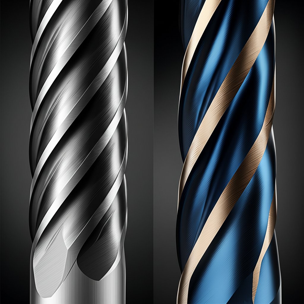
When mechanical rigidity and parameter optimization are not enough to eliminate chatter, the cutting tool itself offers the next level of solutions. Modern end mill technology has evolved specifically to combat self-excited vibrations through advanced geometry. The most effective of these designs are tools that feature unequal flute spacing, also known as variable pitch, and variable helix angles. These features are designed to break up the harmonic resonance that causes chatter.
A standard end mill has flutes that are spaced symmetrically around its diameter. As it rotates, each cutting edge impacts the workpiece at a perfectly regular, rhythmic interval. If this frequency matches the natural frequency of the system, chatter erupts. A variable pitch/helix tool disrupts this rhythm. By slightly altering the spacing between the flutes and the angle of the helix, the tool ensures that the time between each cutting edge impact is constantly changing. This prevents a stable resonant frequency from ever building up, effectively damping chatter at its source.
The number of flutes on an end mill also influences stability. The advice here can seem contradictory but is based on the specific cutting conditions. A higher flute count can provide a smoother cut and better finish by having more cutting edges engaged at any given time, which can stabilize the operation. However, in some cases, particularly in deep slots or with materials that produce large chips, too many flutes can lead to chip packing, which increases cutting forces and can cause chatter. In these situations, an end mill with fewer flutes may perform better. The choice depends on balancing smoothness with effective chip evacuation for the specific application.
To select the best anti-chatter end mill, follow this checklist:
- Look for Variable Geometry: Prioritize tools advertised with "variable pitch," "unequal flute spacing," or "variable helix" features.
- Match Flute Count to Application: Use higher flute counts for finishing and shallow cuts, and consider lower flute counts for deep slotting or materials prone to chip packing.
- Choose the Shortest Length of Cut: Select a tool where the cutting length is only as long as necessary for the deepest feature, as any excess length reduces rigidity.
- Consider Coatings: A modern coating appropriate for the workpiece material will reduce friction, prevent built-up edge, and extend tool life, all of which contribute to a more stable cutting process.
| Feature | Standard End Mill | Variable Helix End Mill |
|---|---|---|
| Harmonics | Creates regular, rhythmic impacts | Disrupts rhythmic impacts, breaking up harmonics |
| Chatter Resistance | Low | High |
| Ideal Application | General purpose, highly rigid setups | Long reach, thin walls, difficult materials |
Frequently Asked Questions
1. What causes CNC chatter?
CNC chatter is caused by self-excited vibrations that occur when the cutting process hits a resonant frequency of the machining system (machine, tool holder, tool, or workpiece). This creates a feedback loop where initial vibrations cause an uneven surface, and cutting that uneven surface reinforces the vibrations, leading to poor surface finish, accelerated tool wear, and a distinct high-pitched sound. Key contributing factors include a lack of rigidity, long tool overhang, incorrect cutting parameters, and inappropriate tool geometry.
2. How do you reduce chattering?
Reducing chatter requires a systematic approach. First, maximize rigidity by using the shortest possible tool, minimizing overhang, and ensuring secure workholding. Second, optimize cutting parameters by making small (5-10%) adjustments to the spindle speed to move out of a resonant frequency. Third, use appropriate tooling, such as end mills with variable pitch/helix designs made to suppress vibration. Finally, employ smart machining strategies like climb milling and constant-engagement toolpaths.
3. How to reduce tool vibration?
Reducing tool vibration is synonymous with reducing chatter. The core strategies are to increase system stiffness and disrupt harmonic resonance. Use high-quality, high-grip tool holders (like hydraulic or shrink-fit) to minimize runout. Select stout tools with the largest possible diameter and shortest possible length. Ensure the workpiece is clamped securely. If vibration persists, adjust spindle speed and feed rate, and consider switching to an anti-vibration end mill.
4. What is the golden rule of milling?
The widely cited "golden rule" of milling is to aim for "thick to thin" chip formation. This is achieved through climb milling, where the cutting edge engages the material at maximum thickness and exits at minimum thickness. This approach directs cutting forces more favorably, increases tool life, and generally produces a better surface finish compared to conventional milling ("thin to thick"). This principle promotes a more stable and efficient cutting action.
-
Posted in
cnc machining, CNC milling, Machining, manufacturing, Tool Chatter
