
How to Calculate Feeds and Speeds: Essential Formulas

TL;DR
To calculate feeds and speeds for machining, you must determine two primary values: spindle speed and feed rate. The essential formulas are Speed (RPM) = (SFM × 3.82) / Tool Diameter and Feed Rate (IPM) = RPM × Chip Load × Number of Teeth. Mastering these calculations is fundamental for optimizing tool life, achieving a high-quality surface finish, and ensuring efficient material removal.
Understanding the Core Concepts: What Are Feeds and Speeds?
Before applying any formulas, it's critical to understand the foundational terms that govern every milling operation. Feeds and speeds are not arbitrary numbers; they are precise variables that dictate the interaction between the cutting tool and the workpiece. Incorrect values can lead to tool breakage, poor part quality, and inefficient production. The two main components are speed and feed, each with its own key metrics.
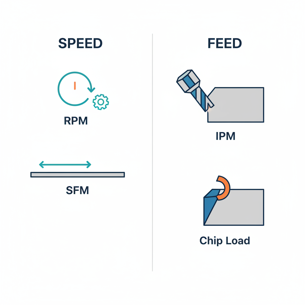
Speed refers to how fast the cutting tool rotates in the spindle and how quickly it moves across the material's surface. It is defined by two related terms:
- Surface Feet per Minute (SFM): This is the speed at which the cutting edge travels across the workpiece surface. SFM is a constant value based on the material being cut and the tool material (e.g., carbide, high-speed steel). It is a property of the material, not a machine setting. Tooling manufacturers provide SFM recommendations in charts for various materials, as seen on resources from suppliers like Whitney Tool.
- Revolutions Per Minute (RPM): This is the actual speed of the spindle, indicating how many full rotations the tool makes in one minute. RPM is the value you program into the CNC machine. It is calculated based on the recommended SFM and the specific diameter of your cutting tool.
Feed refers to the rate at which the cutting tool is advanced into the workpiece. It determines how much material is removed with each pass and is defined by the following terms:
- Chip Load or Feed Per Tooth (FPT/IPT): This is the thickness of material removed by a single cutting edge (or flute) in one revolution. It's a critical value provided by tooling manufacturers that directly impacts tool life and surface finish. A chip load that is too high can overwhelm the tool and cause it to break, while a chip load that is too low can cause rubbing, chatter, and premature tool wear.
- Inches Per Minute (IPM): This is the overall feed rate of the tool through the material, measured in inches per minute. It is the final feed rate value programmed into the machine and is calculated using the RPM, chip load, and the number of teeth on the cutter.
Ultimately, the goal is to balance these variables perfectly. The correct SFM ensures the tool cuts the material at an optimal thermal rate, while the correct chip load ensures each tooth takes a proper-sized bite. These concepts are the essential building blocks for the calculations that follow, transforming theoretical recommendations into practical machine settings.
How to Calculate Spindle Speed (RPM)
Calculating the correct spindle speed (RPM) is the first critical step in setting up any machining operation. This value ensures the tool is rotating at the optimal rate to efficiently cut a specific material without generating excessive heat or wear. The calculation directly translates the material-specific SFM into a machine-specific RPM based on your tool's diameter.
The primary formula for calculating spindle speed is:
Speed (RPM) = (SFM × 3.82) / D
Let's break down each component of this formula:
- SFM (Surface Feet per Minute): This is the recommended cutting speed for the combination of your workpiece material and cutting tool material. You must look this value up in a chart provided by your tooling manufacturer or in a machining data handbook. For example, 6061 aluminum might have a recommended SFM of around 1000 when using a carbide end mill.
- 3.82: This is a constant used for inch-based calculations. It is derived from the formula (12 / π) and simplifies the conversion of feet (from SFM) to inches (from the tool diameter).
- D (Tool Diameter): This is the outside diameter of your cutting tool, measured in inches.
To illustrate, let's use a practical example. Imagine you are milling a block of 6061 Aluminum with a 0.5-inch diameter carbide end mill. The tooling manufacturer recommends an SFM of 1000 for this application. The calculation would be:
RPM = (1000 SFM × 3.82) / 0.5 in. = 7640 RPM
This result, 7640 RPM, is the spindle speed you would program into your CNC machine. It's important to note that factors like the tool's coating, the use of coolant, and the machine's rigidity can influence the starting SFM value. Always begin with the manufacturer's recommendation as a safe and effective starting point.
Follow these steps to calculate your spindle speed:
- Identify your workpiece material (e.g., 304 Stainless Steel, 6061 Aluminum).
- Identify your cutting tool's material (e.g., Uncoated Carbide, High-Speed Steel).
- Look up the recommended SFM for that material combination from a reliable source like a manufacturer's speeds and feeds chart.
- Measure the diameter (D) of your cutting tool in inches.
- Insert these values into the formula to calculate your target RPM.
How to Calculate Feed Rate (IPM)
Once you have determined the optimal spindle speed (RPM), the next step is to calculate the feed rate in Inches Per Minute (IPM). This value dictates how fast the tool moves through the workpiece and is essential for achieving the correct chip thickness. A proper feed rate ensures efficient material removal without causing tool deflection or breakage.
The standard formula for calculating the feed rate is:
Feed Rate (IPM) = RPM × FPT × Z
Here is a breakdown of the variables in this equation:
- RPM (Revolutions Per Minute): This is the spindle speed you calculated in the previous section.
- FPT (Feed Per Tooth): Also known as chip load or IPT (Inches Per Tooth), this is the recommended amount of material each flute of the tool should remove per revolution. This value is provided by the tooling manufacturer and depends on the tool diameter, material, and type of operation (e.g., roughing, finishing).
- Z (Number of Teeth): This is the number of cutting edges, or flutes, on your tool.
Continuing our example from the previous section, we have a calculated RPM of 7640. Let's assume we are using a 4-flute end mill, and the manufacturer recommends a chip load of 0.004 inches per tooth for this application. The calculation would be:
IPM = 7640 RPM × 0.004 FPT × 4 Flutes = 122.24 IPM
The result, 122.24 IPM, is the feed rate you would program into the machine. As explained in detailed guides like Speeds and Feeds 101, finding the right chip load is a critical balance. Too large a chip load can cause poor chip evacuation and tool failure, while too small a chip load can lead to rubbing, chatter, and excessive heat, which dulls the tool prematurely.
To calculate your feed rate, follow this process:
- Use the RPM you calculated in the previous step.
- Find the recommended chip load (FPT or IPT) for your specific tool, material, and operation from the tooling manufacturer's data.
- Count the number of teeth (Z) on your cutting tool.
- Multiply these three values (RPM × FPT × Z) to determine your feed rate in IPM.

Adapting Calculations for Different Operations and Conditions
While the core formulas for RPM and IPM provide a solid foundation, real-world machining requires adapting these calculations for different operations and accounting for practical limitations. The principles remain the same, but the inputs and considerations change for operations like drilling and turning, and advanced concepts like chip thinning can significantly impact results.
Different machining operations require slight modifications to the standard formulas. For precision-engineered components, understanding these nuances is key. Companies specializing in advanced manufacturing, such as XTJ CNC milling, leverage these precise calculations to deliver parts with tight tolerances across a wide range of materials. Their expertise in applying these principles ensures optimal outcomes for everything from rapid prototypes to production runs.
Here’s how calculations differ across common operations:
| Operation | Key Variable for Speed (RPM) | Key Variable for Feed Rate | Formula Notes |
|---|---|---|---|
| Milling | Tool Diameter (D) | Feed Per Tooth (FPT) | IPM = RPM × FPT × Number of Teeth |
| Drilling | Drill Diameter | Inches Per Revolution (IPR) | IPM = RPM × IPR. Feed is based on the tool's advance per full rotation. |
| Turning | Workpiece Diameter | Inches Per Revolution (IPR) | RPM is based on the diameter of the part being turned, not the stationary tool. |
Beyond the operation type, machinists must consider advanced factors. One critical concept is Chip Thinning, also known as radial engagement feed adjustment. As detailed in resources from specialists like Dapra, when the radial width of cut is less than half the tool's diameter, the actual chip thickness becomes smaller than the programmed FPT. To compensate and maintain the desired chip thickness, the feed rate must be increased. Another practical issue is the Spindle Speed Cap. Sometimes, calculations for small-diameter tools in soft materials yield an RPM that exceeds the machine's maximum capability. In this case, you must run at the machine's maximum RPM and proportionally reduce the feed rate to maintain the correct chip load.
Ultimately, all calculations provide a starting point. Experienced machinists use these figures and then listen to the machine, observe the chips, and inspect the surface finish to fine-tune the parameters for optimal performance. These formulas are the scientific basis, but hands-on experience is what perfects the art of machining.
Frequently Asked Questions
1. How to calculate speeds and feeds for drills?
Calculating speeds and feeds for drills follows similar principles to milling but uses different feed metrics. The spindle speed formula remains the same: RPM = (SFM × 3.82) / Drill Diameter. However, the feed rate is typically expressed in Inches Per Revolution (IPR). To find the feed rate in Inches Per Minute (IPM) for your machine, you use the formula: IPM = RPM × IPR. The IPR value is provided by the drill manufacturer based on the drill diameter and workpiece material.
2. How do you calculate feed rate in CNC?
To calculate the feed rate for a CNC milling operation, you use the formula: Feed Rate (IPM) = RPM × Chip Load × Number of Flutes. First, you determine the correct RPM based on the material's SFM and the tool's diameter. Next, you find the recommended chip load (also called feed per tooth or FPT) from the tooling manufacturer's specifications. Finally, you multiply the RPM by the chip load and the number of flutes (teeth) on the cutter to get the final feed rate in inches per minute (IPM), which is then programmed into the CNC controller.
-
Posted in
CNC, feeds and speeds, Machining, Milling, rpm calculation


