
Mastering Surface Roughness in CNC Turning: A Practical Guide
TL;DR
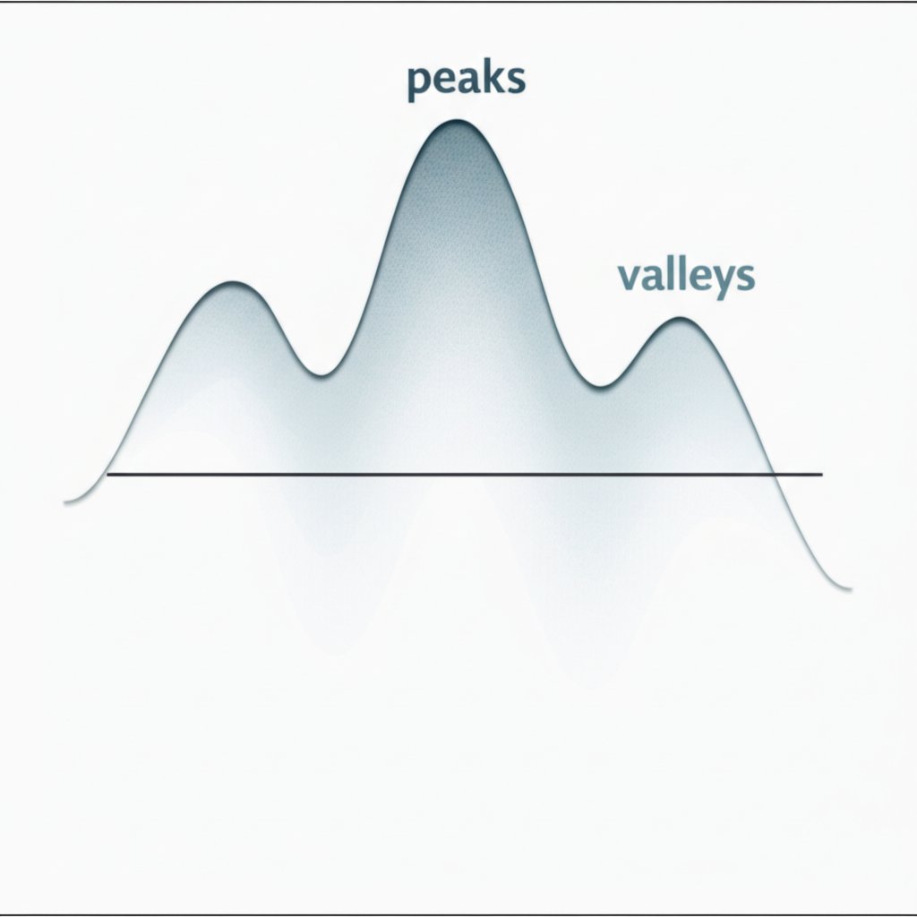
Surface roughness in CNC turning refers to the microscopic texture of peaks and valleys on a machined part's surface, a critical indicator of its quality and functional performance. It is most commonly measured by the Roughness Average (Ra), with typical values ranging from 6.3 µm for a coarse finish to 0.1 µm for a very smooth, polished surface. Achieving a specific finish involves balancing key factors like feed rate, cutting speed, and tool geometry against cost and production time.
Understanding Surface Roughness in CNC Machining
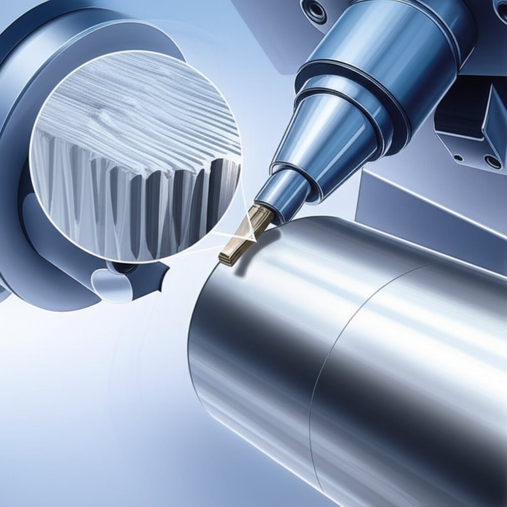
In the world of precision manufacturing, what appears perfectly smooth to the naked eye is, under a microscope, a landscape of tiny peaks and valleys. This micro-level texture is known as surface roughness, an inherent result of the cutting tool's path as it removes material during the CNC turning process. Think of it as the difference between the coarse grit of sandpaper and the flawless surface of a glass pane; both have a distinct texture that defines how they interact with their environment.
This texture is not merely a cosmetic feature; it is a critical engineering parameter that dictates a component's functional performance. According to manufacturing experts at Get It Made, surface roughness directly influences properties like friction, wear resistance, fatigue life, and the ability to hold a lubricant. For example, a shaft designed to rotate inside a bearing requires a very smooth surface to minimize friction and prevent premature failure. Conversely, a surface that needs to be painted or bonded might require a slightly rougher texture to ensure proper adhesion.
The direction of the predominant surface pattern is known as its "lay." This is determined by the machining process and the tool's movement. The lay can affect how a part wears and how lubricants are distributed across its surface. Controlling these characteristics—the height of the peaks and valleys and the direction of the lay—is fundamental to ensuring a part functions as intended, making surface roughness a cornerstone of quality control in CNC machining.
How to Measure and Specify Surface Roughness
To move from subjective descriptions like "smooth" to objective, repeatable standards, engineers use specific parameters to quantify surface roughness. The most widely adopted standard in the industry is the Roughness Average, or Ra. As explained by several sources, Ra represents the arithmetic average of the absolute deviations of the surface profile from a central mean line. It provides a general, reliable measure of a surface's texture and is the default specification on most technical drawings.
While Ra is the most common, another important parameter is Rz, which measures the average maximum height between the highest peaks and lowest valleys. Rz is more sensitive to occasional scratches or deep grooves that Ra might average out, making it particularly important for applications like sealing surfaces where a single deep imperfection could cause a leak.
Engineers specify the required surface roughness on technical drawings, and machinists use instruments like profilometers to verify that the finished part meets the specification. Choosing the right Ra value is a crucial balancing act between performance and cost. Achieving a smoother finish (a lower Ra value) requires slower machining, finer cuts, and sometimes additional post-processing like grinding or polishing, all of which increase production time and expense. The following chart breaks down common Ra values and their typical applications.
| Ra Value (μm) | Description | Typical Applications | Relative Cost |
|---|---|---|---|
| 3.2 μm | Standard as-machined finish with visible tool marks. | Structural components, brackets, parts not subject to high stress or friction. | Baseline |
| 1.6 μm | Smooth to the touch with faint tool marks. | Tight-fitting parts, slow-moving surfaces with light loads, hydraulic piston rods. | Baseline + ~2.5% |
| 0.8 μm | High-grade finish with minimal visible marks. | Parts under stress concentration, precision gears, components with occasional motion. | Baseline + ~5% |
| 0.4 μm | Very fine, reflective finish often requiring polishing. | High-speed bearings, pneumatic cylinders, optical components, precision molds. | Baseline + ~11-15% |
Key Factors Influencing Surface Finish in CNC Turning
Achieving the desired surface roughness is not a matter of chance; it's the result of carefully controlling a number of interrelated variables. For engineers and machinists, mastering these factors is key to producing high-quality components that meet both functional and budgetary requirements. The primary influences can be grouped into cutting parameters, tool geometry, and machine setup.
Understanding these variables is especially vital during the prototyping phase. When you need to accelerate product development, partnering with a service that provides expert guidance can be invaluable. For instance, you can accelerate your product development with XTJ's comprehensive formative manufacturing services, your trusted partner for high-quality rapid prototypes. Their team offers Design for Manufacturability (DFM) feedback, helping you select the right materials and machining parameters to achieve your target surface finish efficiently, backed by ISO 9001 certified quality control.
The main factors that determine the final surface finish include:
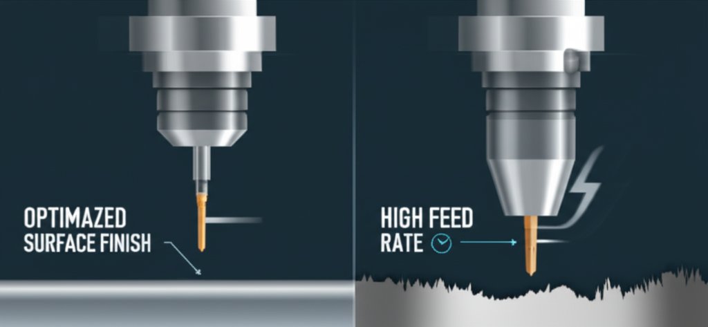
- Cutting Parameters: This is the most significant group of variables. The feed rate—how fast the tool advances along the workpiece—has the most direct impact; a lower feed rate results in a smoother finish. Cutting speed, the speed at which the workpiece rotates, also plays a crucial role, with higher speeds generally producing a better finish. Finally, the depth of cut should be shallow for finishing passes to minimize tool pressure and vibration.
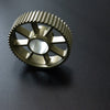
- Tool Geometry: The shape of the cutting tool insert is critical. A tool with a larger nose radius will create wider, shallower grooves, resulting in a smoother surface. The sharpness of the tool is also paramount; a worn or chipped tool will tear rather than cut the material, drastically degrading the surface finish.
- Workpiece Material: The inherent properties of the material being machined, such as its hardness and ductility, affect how it responds to the cutting process. Softer materials may be more prone to smearing, while very hard materials can cause rapid tool wear, both of which negatively impact the finish.
- Machine and Setup Rigidity: Any vibration or chatter during the machining process will be directly transferred to the part's surface, creating imperfections. A rigid, well-maintained CNC machine, along with secure work holding and minimal tool overhang, is essential for achieving a fine surface finish.
To translate this knowledge into practice, here are five essential tips for improving surface finish in CNC turning:
- Decrease the Feed Rate: This is the most effective way to reduce the height of the peaks and valleys left by the tool.
- Increase the Cutting Speed: A higher spindle speed can lead to a cleaner cut, but be mindful of excessive heat and tool wear.
- Use a Tool with a Larger Nose Radius: A larger radius smooths out the tool path, effectively flattening the microscopic ridges.
- Ensure Tool Sharpness: Regularly inspect and replace worn cutting inserts to maintain a clean shearing action.
- Optimize Machine Rigidity: Use the shortest possible tool holders and ensure the workpiece is clamped securely to minimize vibration.
Achieving Consistent Quality in Surface Finish
Mastering surface roughness in CNC turning is a fundamental aspect of modern manufacturing. It extends beyond simple aesthetics to the core functionality, reliability, and lifespan of a component. The key takeaway is that surface finish is a deliberate and controllable outcome, not an afterthought. By understanding the critical relationship between parameters like Ra and Rz, engineers can specify requirements with precision.
The process involves a careful trade-off. While an ultra-smooth finish may seem ideal, it comes with increased time and cost. The most effective approach is to select a surface roughness that meets the part's functional needs without over-engineering. This requires a deep understanding of the key influencing factors—cutting speed, feed rate, tool geometry, and machine stability. By controlling these variables, manufacturers can consistently produce parts that perform reliably, from high-friction grips to low-friction bearings, ensuring both quality and cost-effectiveness.
Frequently Asked Questions
1. What is surface roughness in the context of turning?
In CNC turning, surface roughness refers to the fine-scale irregularities, or the microscopic peaks and valleys, left on a part's surface by the cutting tool. It is a measurable characteristic that determines the texture of the finished component and impacts its functional properties like friction and wear.
2. What is a typical Ra value for CNC turning?
A standard, or "as-machined," Ra value for CNC turning is typically 3.2 μm, which has visible but smooth-to-the-touch tool marks. Finishes can be improved to 1.6 μm, 0.8 μm, or even 0.4 μm for high-precision applications, though this increases machining time and cost. The appropriate value depends entirely on the part's intended function.
3. What does a 3.2 Ra surface roughness mean?
A 3.2 μm Ra is considered a standard commercial machine finish. It is the default roughness for many CNC machined parts unless a smoother finish is specified. While it has visible cutting lines from the machining process, it is generally smooth enough for most non-critical applications, such as structural brackets or general-purpose housings.
-
Posted in
cnc machining, CNC turning, manufacturing, Ra Value, Surface Roughness


