What Is GD&T in CNC Machining and When Do You Need It?
When designing CNC machined parts, hitting correct dimensions is only half the battle. A part can pass all linear dimension checks yet still fail assembly or function. This is where Geometric Dimensioning and Tolerancing (GD&T) comes in.
GD&T is a standardized engineering system to define allowable variation of a part’s geometry: form, orientation, location and runout. It gives designers, machinists and inspectors a shared language for critical precision requirements. Unlike basic ± tolerances, GD&T describes how features relate to each other and how the part works inside an assembly. It is essential for parts needing precise alignment, positioning and interchangeability.
You do not need GD&T on every CNC component. Correctly applying it improves quality, cuts redundant inspection work and keeps manufacturing costs controlled. If you are sourcing precision machined parts with strict geometric requirements, work with a reliable supplier for precision CNC machining with GD&T control:xtjmachining.com
1. Core Basics of GD&T
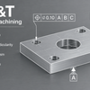
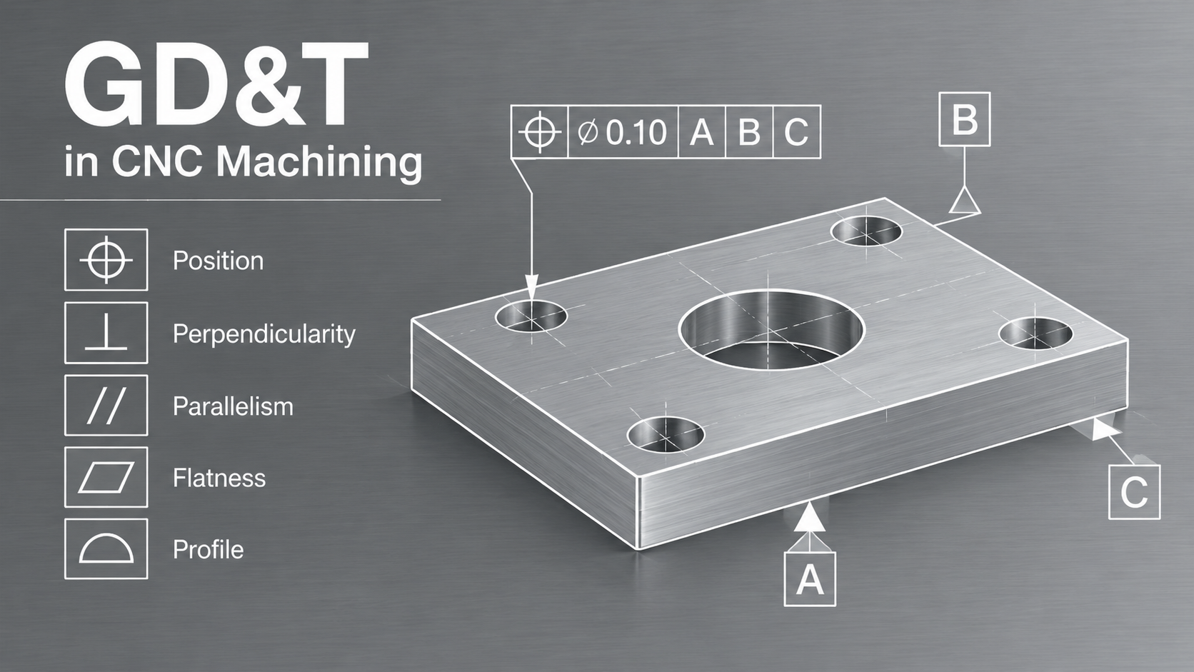
GD&T uses standardized symbols, feature control frames, datums and tolerance zones to define acceptable deviation from the ideal geometry. Two mainstream standards are ASME Y14.5 and ISO GPS; always mark the standard on drawings to avoid misinterpretation.
GD&T characteristics fall into 5 groups:
- Form: Straightness, flatness, circularity, cylindricity
- Orientation: Parallelism, perpendicularity, angularity
- Location: Position, concentricity, symmetry
- Profile: Profile of a line, profile of a surface
- Runout: Circular runout, total runout
The most frequently used in CNC shops:
- Flatness: For sealing surfaces, base plates and fixture mounting faces
- Perpendicularity: Ensures 90° alignment between mating faces
- Parallelism: For guide rails, sliding parts and parallel mounting plates
- Position: Critical for dowel holes, bolt patterns and threaded holes
- Runout: Used for rotating parts like shafts, spindles and bearing seats
2. GD&T vs Standard Dimensional Tolerances
Standard tolerances control individual sizes, e.g. 20 ±0.05 mm. They cannot guarantee shape, straightness or relative position between features. GD&T controls geometric relationships via datums and symbol rules. It is designed for complex assemblies where feature alignment matters.
表格
| Comparison | Standard Tolerances | GD&T |
|---|---|---|
| Focus | Single dimension variation | Geometry + feature relationships |
| Reference | No datums required | Datum-based measurement |
| Best for | Simple low-tolerance parts | Precision assembly, rotating and sealing parts |
3. When Do You Need GD&T?
Add GD&T controls in these 5 scenarios:
- Multiple mating features: Hole patterns and locating pins that must align during assembly
- Precision alignment parts: Automation, optical equipment and positioning components
- Rotating components: Shafts and bearing housings to reduce vibration and wear
- Sealing, sliding or load-bearing surfaces: Flatness, cylindricity for functional performance
- High interchangeability batches: Parts that fit together without hand fitting
4. How GD&T Changes Machining & Inspection
GD&T decides workpiece setup, fixturing strategy, toolpaths and inspection methods.
- Machining: Datums decide clamping references; tight position/runout needs extra finishing passes
- Inspection tools: CMM for position and profile; optical comparators for small features; dial indicators for runout checks
5. Practical Steps to Add GD&T on Drawings
- Pick only functionally critical features
- Select datums matching how the part is assembled
- Choose matching GD&T symbols (flatness for seals, position for hole patterns)
- Set realistic tolerance values — over-tight specs raise cost
- Mark the applicable standard on the drawing
6. Does GD&T Raise CNC Machining Cost?
GD&T itself does not automatically increase cost. Unnecessarily tight geometric tolerances do: extra setup, CMM inspection, longer cycle time and higher scrap risk.
Well-designed GD&T actually reduces cost by eliminating assembly failures and ambiguous drawing requirements. Only apply strict controls where function demands it.
Conclusion
GD&T is a powerful communication tool for precision CNC drawings. It goes beyond simple size tolerances to govern shape, orientation and position between features. It is ideal for mating assemblies, rotating parts and high-precision equipment, but unnecessary for simple low-demand parts. Reasonable GD&T settings balance performance, quality and production cost.
FAQ
- What is the difference between standard tolerances and GD&T? Standard tolerances control individual dimensions. GD&T controls geometric properties such as flatness and position, plus the spatial relationship between features using datums.
- When should I put GD&T on CNC drawings? Use GD&T for hole patterns, sealing surfaces, rotating shafts and precision alignment parts. Simple prototype parts often only need basic dimensional tolerances.
- Does GD&T make CNC parts more expensive? It may add cost if tolerances are overly strict and require CMM inspection. Proper GD&T prevents assembly rework and avoids over-machining, which can save cost in the long run.