
Essential CNC Machining Design for Manufacturing

TL;DR
Design for Manufacturing (DFM) for CNC machining is the practice of designing parts to optimize for the manufacturing process, significantly reducing costs and production time. Key CNC machining design for manufacturing principles include adding radii to all internal corners, maintaining wall thicknesses above 0.8mm for metal and 1.5mm for plastic, and using standard sizes for features like holes and threads to align with common tooling.
What is Design for Manufacturing (DFM) in CNC Machining?
Design for Manufacturing, commonly known as DFM, is a proactive engineering practice focused on designing products to be as easy and economical to manufacture as possible. In the context of Computer Numerical Control (CNC) machining, this means creating a part's geometry with the capabilities and limitations of milling machines and lathes in mind. Since CNC is a subtractive process—where material is precisely removed from a solid block to reveal the final shape—every design choice directly impacts tool selection, machining time, and ultimately, the final cost.
Applying DFM principles is a critical step that bridges the gap between a digital CAD model and a physical, high-quality component. By considering the manufacturing process during the design phase, engineers can prevent common issues like tool breakage, material warping, and excessive machining time. According to a guide from Protolabs Network, optimizing a design for the basic mechanics of the cutting process is essential for achieving the best results. This foresight ensures that the part is not just theoretically perfect but practically manufacturable.
The primary benefits of integrating DFM into your CNC machining workflow are substantial and directly address core business objectives:
- Cost Reduction: Simplifies geometry, reduces the need for special tooling, and minimizes machining time, which is a primary cost driver.
- Improved Part Quality: Designs that respect the physics of machining suffer less from issues like tool chatter or material deformation, resulting in better surface finishes and dimensional accuracy.
- Faster Production Times: Eliminating complex or hard-to-machine features means fewer machine setups and faster cycle times, accelerating the entire production schedule.
- Enhanced Repeatability: Well-designed parts can be produced consistently across large batches, as the process is more stable and less prone to error.
Key Geometric Considerations for Manufacturability
The geometry of a part is the most significant factor in its manufacturability. How an engineer designs walls, corners, and other features dictates the type of tools required, the number of operations, and the overall time spent on the machine. Adhering to a few fundamental geometric rules can dramatically improve production outcomes.
Wall Thickness
One of the most common design flaws is creating walls that are too thin. Thin walls are susceptible to vibration (chatter) during machining, which can lead to dimensional inaccuracies and a poor surface finish. They can also warp or break, especially in plastics which may soften from the heat of the cutting tool. As a best practice, it's crucial to design walls with sufficient thickness to withstand the forces of machining. General guidelines, such as those provided by Norck, recommend a minimum wall thickness of 0.8 mm for metals and 1.5 mm for plastics. While absolute minimums can be lower (0.5 mm for metal, 1.0 mm for plastic), pushing these limits increases risk and cost.
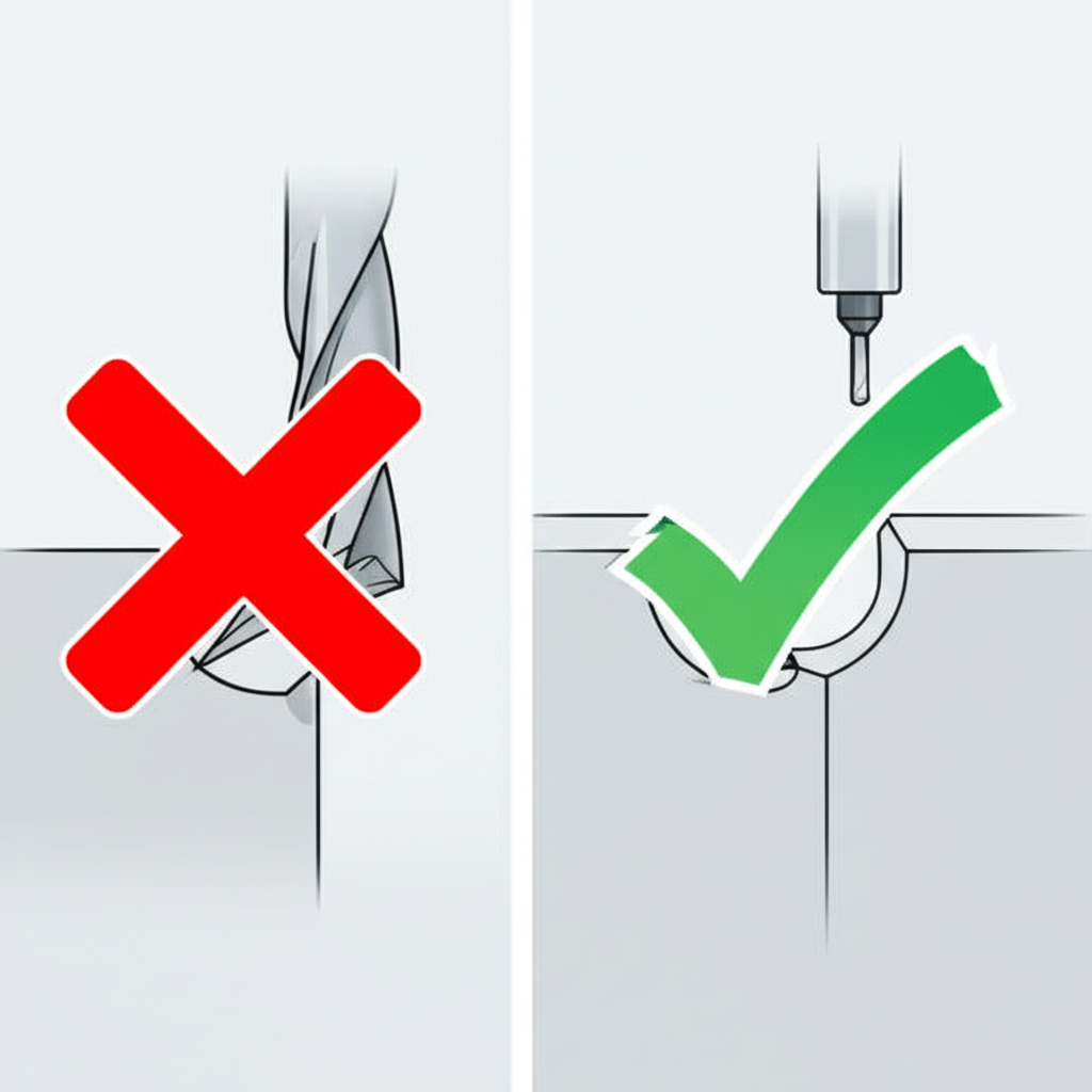
Internal Corners and Radii
CNC milling tools are cylindrical, meaning they cannot create perfectly sharp 90-degree internal corners. The tool will always leave a radius. Attempting to create a very small radius requires a very small tool, which is fragile, slow, and prone to breaking. Therefore, a critical rule in CNC machining design is to add a generous radius to all internal vertical corners. A good rule of thumb is to make the corner radius at least one-third of the cavity's depth. For example, as noted in a checklist by Fast Radius, increasing the corner radii slightly larger than the tool's radius allows the tool to move more smoothly, improving the surface finish and reducing tool wear. For external corners, using a chamfer is often more cost-effective than a radius.
Designing Functional Features
Beyond basic geometry, specific features like pockets, holes, and threads have their own set of design rules. Optimizing these features is essential for creating functional and cost-effective parts.
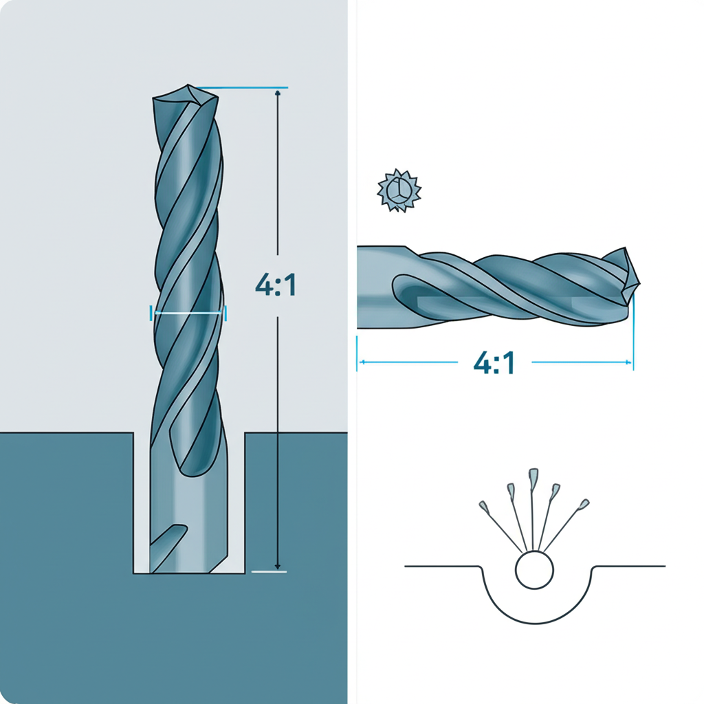
Pockets and Cavities
Deep, narrow pockets are challenging and expensive to machine. They require long, thin cutting tools that are prone to deflection and breakage, and chip evacuation becomes a significant problem. A widely accepted guideline is to limit the depth of any cavity to four times its width. If a deep pocket is unavoidable, designing it with variable depth or providing ample space can mitigate some of these challenges. As a general rule, pocket depth shouldn't exceed three times the diameter of the tool used for the final feature.
Holes
Holes are a fundamental feature, but their design greatly impacts cost. Whenever possible, design holes with standard drill bit sizes. Using non-standard sizes requires an end mill to interpolate the hole, which takes more time than drilling. For deep holes, the recommended maximum depth is typically four to ten times the hole's diameter. It is also important to ensure that the start and end faces for a hole are perpendicular to the drill axis to prevent the tool from wandering and to avoid creating difficult-to-remove burrs.
Threads
For threaded features, it's best to use standard thread sizes like UNC, UNF, or metric standards. This ensures standard taps and dies can be used. The effective length of a thread is often shorter than people assume; most of the holding force is concentrated in the first few turns. A thread length of 1.5 to 3 times the hole's nominal diameter is usually sufficient. For blind holes, it is critical to design an unthreaded length at the bottom of the hole, at least half the diameter, to give the tap clearance and prevent breakage.
Advanced Design Principles
Once the primary features are optimized, considering advanced topics like tolerances, material selection, and text can further refine the design for manufacturing, ensuring a balance between performance and cost.
Tolerances
Tolerances define the acceptable dimensional variance of a part. While CNC machines are capable of achieving very high precision, specifying unnecessarily tight tolerances significantly increases manufacturing costs due to longer machining times, more frequent inspections, and higher scrap rates. A standard machining tolerance of ±0.13mm (±0.005 in.) is common and cost-effective for most applications. Tighter tolerances should only be applied to critical features and interfaces where precision is functionally necessary. Always question whether a feature truly needs a high level of precision before adding it to the drawing.
Material Selection
The choice of material has a profound impact on the design and machining process. Harder materials like stainless steel or titanium are more difficult and time-consuming to machine than softer materials like aluminum or plastics like POM (Delrin). Material properties also influence design rules; for example, the minimum wall thickness is greater for plastics than for metals due to their lower rigidity and susceptibility to heat. When selecting a material, consider its machinability alongside its mechanical properties to find the right balance for your application. When high precision across a wide range of materials is required, partnering with an expert service can be invaluable. For instance, services like XTJ CNC Machining handle over 30 materials with tight tolerances, simplifying the process of turning complex designs into production-ready parts.
Text and Lettering
Adding text or logos to a machined part requires careful design. Engraved (recessed) text is preferable to raised (embossed) text because it involves removing less material. For clarity, use a simple sans-serif font like Arial or Verdana with a font size of 20 points or larger. The width of the text strokes must be large enough for the cutting tool to fit. Protolabs suggests a minimum width of 0.457mm for plastics and soft metals. Following these guidelines ensures the text is legible and manufacturable without requiring specialized, costly operations.
From Design to Production-Ready Part
Mastering CNC machining design for manufacturing is not about memorizing a rigid set of rules, but about understanding the relationship between design choices and the physical process of machining. By internalizing key principles—such as favoring radii over sharp corners, maintaining robust wall thicknesses, and designing features around standard tools—you can dramatically reduce costs, shorten lead times, and improve the quality of your final components. An optimized design is one that achieves its functional purpose while being as simple and efficient as possible to produce. This DFM mindset is the foundation of successful and scalable manufacturing.
Frequently Asked Questions
1. How do you design for CNC machining?
To design for CNC machining, focus on principles that simplify the manufacturing process. Key tips include avoiding excessively thin walls, using radii for all internal vertical edges, designing cavities with depth-to-width ratios no greater than 4:1, using standard sizes for holes and threads, and specifying tight tolerances only when absolutely necessary. These practices reduce machining time, tool wear, and overall cost.
2. What is CNC machining in manufacturing?
Computer Numerical Control (CNC) machining is an automated manufacturing process where pre-programmed computer software dictates the movement of factory tools and machinery. It is a subtractive process, meaning it shapes a part by removing material from a solid block of metal or plastic using cutting tools like mills, lathes, and drills. It is known for its high precision, repeatability, and versatility with a wide range of materials.
-
Posted in
cnc machining, DFM, engineering, manufacturing design, subtractive manufacturing