
Essential Rules for Designing Threads for CNC Machined Parts
TL;DR
Properly designing threads for CNC machined parts is critical for ensuring manufacturability, strength, and cost-effectiveness. The key is to apply Design for Manufacturability (DFM) principles, which involves using standard thread sizes, specifying thread depth instead of drill depth for blind holes, and providing adequate relief for external threads. Clear communication of these specifications in CAD models and technical drawings is essential to prevent costly production errors.
Fundamental Principles of Thread Design for Manufacturability
Design for Manufacturability (DFM) is a framework that prioritizes ease of manufacturing in the product design phase. When applied to threading, DFM aims to create parts that are not only functional but also efficient and economical to produce. Missteps in thread design can lead to broken tools, rejected parts, and significant delays. Adhering to a few fundamental principles can bridge the gap between design intent and the reality of the shop floor, ensuring a smoother production process.
The cornerstone of DFM for threads is the use of standard sizes. Opting for common thread series like Unified National Coarse (UNC) or Unified National Fine (UNF) in imperial units, or standard metric sizes, is almost always the best approach. Machinists have standard taps and dies readily available for these sizes, which reduces setup time and tooling costs. Conversely, custom or non-standard threads require specialized, expensive tooling and more complex machine programming, driving up both cost and lead time. Coarse threads (like UNC) are generally more cost-effective and robust, making them a suitable default for most applications.
Material choice also plays a crucial role. The hardness and machinability of a material directly impact how it can be threaded. Harder metals may require slower cutting speeds or more durable tooling, while softer materials like aluminum and some plastics can be prone to thread wear or stripping. In cases where threads in softer materials will see high use, designers should consider using thread inserts. According to Protolabs, these are hardened metal coils inserted into a pilot hole to provide a durable, wear-resistant thread, extending the life of the part. When dealing with over 30 material types and tight tolerances down to +/- 0.005mm, partnering with a specialized service like XTJ can ensure your design intent is perfectly realized across various materials.
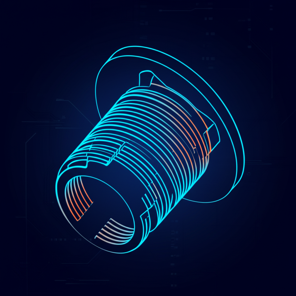
Best Practices for Designing Internal Threads (Tapped Holes)
Internal threads, created by tapping a hole, are common features in CNC machined parts but are also a frequent source of manufacturing issues. Designing them correctly requires careful attention to depth, clearance, and diameter to avoid tool breakage and ensure the final part functions as intended. Following a few key best practices can prevent the most common and costly errors associated with tapped holes.
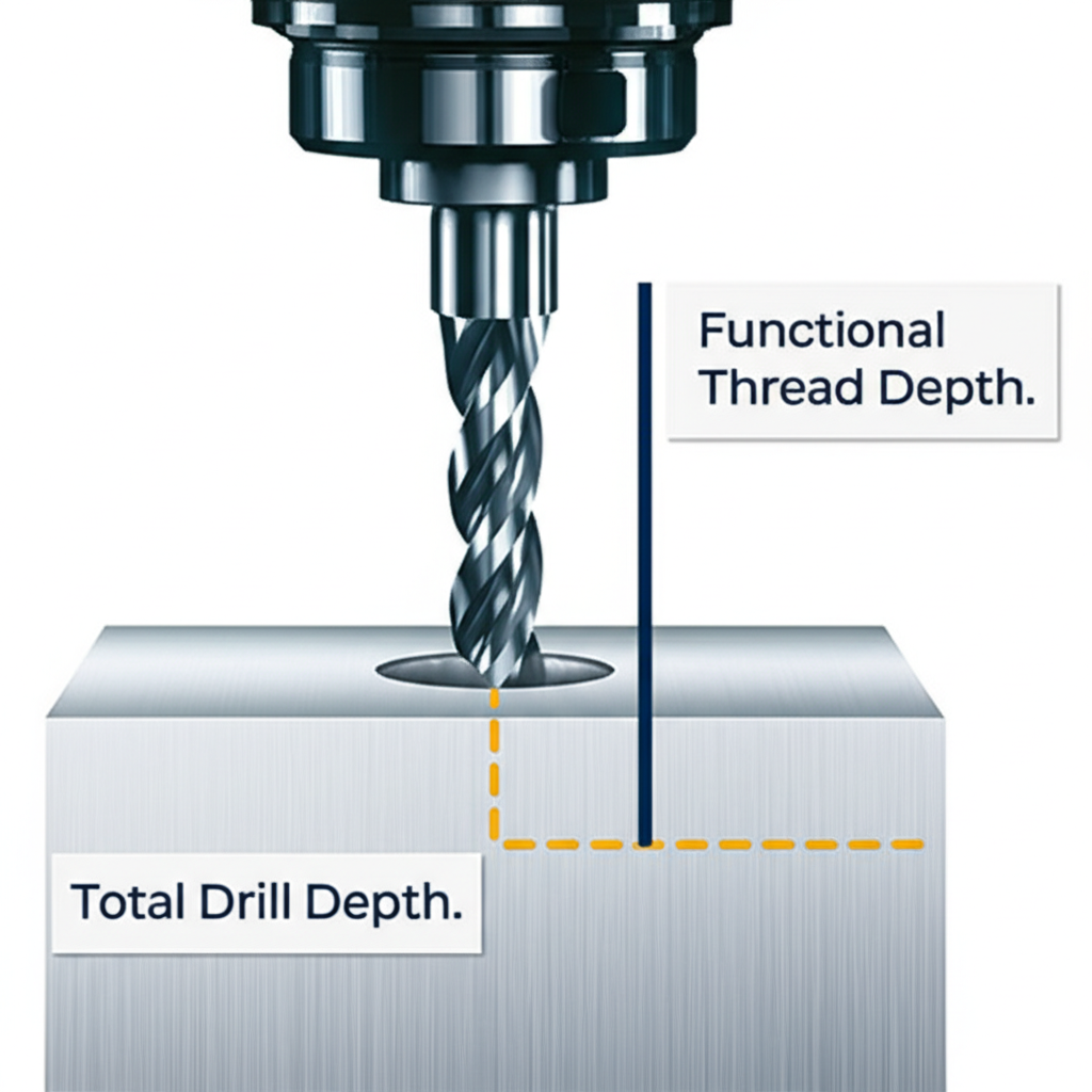
One of the most critical rules is to specify thread depth, not drill depth. As explained by Reata Engineering, thread depth is the functional length of usable thread, while drill depth is the total depth of the hole created before tapping. The drill depth must always be greater than the thread depth to provide clearance for the tap and space for chips to accumulate, especially in blind holes (holes that do not go all the way through the part). Forcing a tap to the bottom of a hole without clearance will cause it to break. A good rule of thumb is to design an unthreaded length at the bottom of a blind hole that is at least 1.5 times the thread's nominal diameter.
Another important consideration is to avoid excessively deep threads. A common misconception is that longer threads are always stronger. In reality, most of the load on a fastener is concentrated on the first few threads. Designing threads deeper than 1.5 to 2 times the major diameter of the thread offers diminishing returns in strength while significantly increasing machining time, cost, and the risk of tap breakage. For most applications, a thread engagement length of 1x the diameter in steel and 2x in aluminum is sufficient. Finally, including a countersink or a chamfer at the entrance of a tapped hole helps guide the tap and the mating screw, preventing cross-threading and ensuring a clean start.
Best Practices for Designing External Threads
External threads, like those on bolts and shafts, have their own set of design considerations. While often perceived as simpler to machine than internal threads, overlooking key details can lead to manufacturing failures and parts that do not assemble correctly. Proper design focuses on tool clearance, thread length, and smooth transitions to ensure both manufacturability and functional integrity.
A crucial feature for external threads is the thread relief or undercut. When an external thread terminates against a shoulder (a larger diameter feature), the cutting tool needs a place to exit the cut cleanly. Without a small groove, or undercut, at the end of the thread, the tool cannot complete the final thread properly, resulting in an incomplete or damaged thread form. Providing this relief ensures a fully formed thread right up to the shoulder and prevents stress concentrations that could lead to part failure.
Similar to internal threads, optimizing thread length is important. Unless the application requires exceptionally high tensile strength, keeping external threads as short as functionally possible is more economical. Shorter threads require less machining time and reduce material waste. It is also good practice to add a chamfer to the beginning of an external thread. This removes the sharp, thin starting thread (a "feather edge"), making it easier to engage with a mating part and reducing the risk of cross-threading or damage during assembly.
Specifying Threads in CAD and Technical Drawings
Clear communication between the designer and the machinist is paramount for successful manufacturing. The CAD model and accompanying technical drawings are the primary tools for conveying design intent. For threaded features, it is essential to provide precise, standardized information to eliminate ambiguity and ensure the final part meets all specifications.
When modeling threads in CAD software, the best practice is to represent them as cosmetic threads rather than modeling the actual helical geometry. Fully modeled threads create very large file sizes and can be misinterpreted by CAM software, which may try to machine each individual crest and root. Instead, designers should model the pilot hole (for internal threads) or the major diameter shaft (for external threads) and use the software's annotation or hole feature tool to create a cosmetic thread callout. This keeps the model simple and relies on standardized notation to define the feature.
The technical drawing must include a standard thread callout for every threaded feature. A typical metric callout like M6 x 1 - 6H contains all the necessary information:
- M6: The major diameter (6mm) and thread series (M for metric).
- 1: The pitch (1mm distance between threads).
- 6H: The thread class, which defines the tolerance and fit. 'H' is for internal threads.
This standardized notation, along with the specified thread depth, gives the machinist everything they need to select the right tools and program the CNC machine correctly, as highlighted by resources from Protolabs Network.
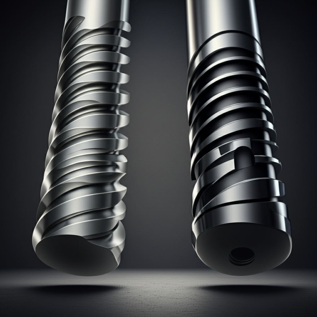
Comparing Threading Methods: Cut Threads vs. Rolled Threads
Threads are typically created in one of two ways: cutting or rolling. Each method has distinct advantages and disadvantages related to strength, surface finish, and cost. Understanding these differences helps designers specify the appropriate manufacturing process for their application, especially in demanding industries like aerospace where performance is critical.
Thread cutting is a subtractive process where a tool physically removes material to form the thread's geometry. This is the most common method used in CNC machining for both internal and external threads. Thread rolling is a forming process where a hardened die is pressed against a workpiece, deforming the surface to create threads without removing material. This process is typically used only for external threads.
The choice between cutting and rolling often depends on the part's performance requirements and production volume. Here is a comparison of the key features:
| Feature | Cut Threading | Rolled Threading |
|---|---|---|
| Process Description | Material is removed with a single-point tool or tap to create the thread profile. Versatile and common in CNC shops. | Threads are formed by displacing material with hardened dies. A chipless, cold-forming process. |
| Strength & Fatigue Life | Good. The process cuts through the material's grain structure, which can create stress risers. | Excellent. The cold-working process strengthens the material and improves fatigue resistance by preserving the grain flow. |
| Surface Finish | Good, but can have microscopic tears or imperfections from the cutting action. | Excellent, typically smoother and more consistent due to the burnishing effect of the dies. |
| Material Suitability | Works with almost any machinable material. | Best suited for ductile materials that can be cold-formed without fracturing. |
| Typical Cost | Lower tooling cost, suitable for low to medium volumes. Slower cycle time per part. | Higher initial tooling cost, but very fast cycle times make it cost-effective for high-volume production. |
In summary, while cut threads are versatile and standard for most CNC applications, rolled threads should be specified for high-strength, high-fatigue applications where production volumes justify the tooling investment.
Frequently Asked Questions
1. What is the most common mistake when designing threads for CNC?
The most common mistake is specifying the drill depth instead of the required thread depth for a blind hole. This creates ambiguity for the machinist and can lead to a tap breaking if there isn't enough clearance at the bottom of the hole. Always define the functional, usable thread length required for your assembly.
2. Why are standard thread sizes so important?
Using standard thread sizes (like UNC, UNF, and metric standards) drastically reduces manufacturing costs and lead times. Machine shops keep standard-sized taps and dies in stock, eliminating the need for expensive custom tooling and complex programming. It is a core principle of Design for Manufacturability (DFM).
3. Should I model the physical threads in my CAD file?
No, it is almost always better to use cosmetic threads or annotations in your CAD model. Modeling the actual helical threads makes file sizes unnecessarily large and can confuse CAM software. Instead, model the simple cylindrical feature (pilot hole or shaft) and use a standard callout on your technical drawing to specify the thread details.
-
Posted in
cnc machining, DFM, mechanical design, tapping, thread design


