
Prepare Your File for Flawless CNC Machining

TL;DR
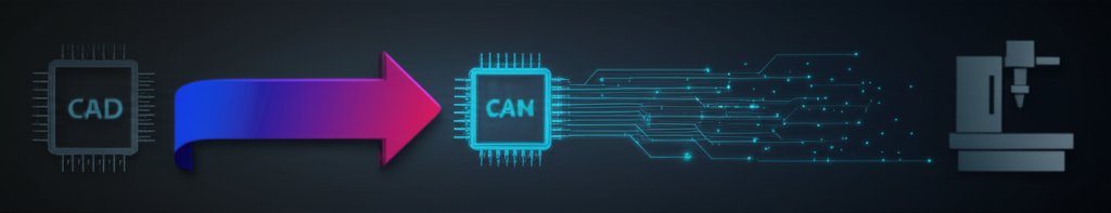
Preparing a file for CNC machining involves a precise workflow. First, you create a 2D or 3D digital model using Computer-Aided Design (CAD) software, focusing on manufacturability. Next, you export this design into a standard vector format like STEP or DXF. Finally, you use Computer-Aided Manufacturing (CAM) software to generate toolpaths and post-process the file into G-code, the language the CNC machine reads to create the physical part.
The Core CNC File Workflow: From CAD to CAM to G-Code
Understanding how to prepare a file for CNC machining begins with grasping the fundamental three-stage process: design (CAD), toolpath generation (CAM), and machine instruction (G-code). This workflow transforms a digital idea into a physical object with precision. Each step is crucial for a successful outcome, and a mistake in one can lead to wasted material and time. Think of it like planning a road trip: your CAD file is the map of your destination, the CAM process is the turn-by-turn GPS directions, and the G-code is the specific instructions you give the driver.
The first stage is Computer-Aided Design (CAD). This is where you create the geometric blueprint of your part. Using software like Fusion 360 or SolidWorks, you draw or model the object with exact dimensions. The primary goal in this phase is to produce a clean, accurate digital representation of the final product. This file contains all the shapes, curves, and holes that will be machined.
Next comes Computer-Aided Manufacturing (CAM). Once your CAD design is complete, you import it into CAM software. Here, you translate the static design into a dynamic set of instructions. You'll define the type of material being cut, select the appropriate cutting tools, set parameters like cutting speed and depth, and generate the toolpaths—the exact route the cutting tool will follow. As detailed in a guide by JLC CNC, this step is where the manufacturing strategy is decided.
The final output of the CAM process is G-code. This is the programming language that CNC machines understand. It consists of a series of coordinates and commands (like G01 for linear movement or M03 to start the spindle) that direct every action of the machine. The CAM software uses a 'post-processor' to translate the toolpaths into the specific G-code dialect your particular CNC machine uses. This file is then loaded into the machine's controller, ready for production.

Step 1: Designing for Manufacturability in the CAD Phase
The quality of your final machined part is determined long before the machine starts cutting; it begins in the CAD phase. Designing for manufacturability (DFM) means creating your digital model with the physical limitations and processes of CNC machining in mind. A beautiful design that is impossible or needlessly expensive to machine is a failed design. Key considerations include material properties, tool access, and assembly requirements.
One of the most critical practices is to ensure your geometry is 'clean'. This means all 2D shapes intended for cutting must be closed vectors with no overlapping or duplicate lines. For 3D models, the geometry should be 'watertight', meaning there are no gaps or holes in the surfaces. As highlighted by the College for Creative Studies, it's also vital to include design clearances. If two parts need to fit together, they cannot be designed with the exact same dimensions; a small gap (e.g., 0.005"-0.012") must be added to account for material variation and tool tolerances.
A comprehensive technical drawing should accompany your CAD file, especially for complex parts. According to manufacturing service Protolabs Network, while the 3D model provides the geometry, the 2D technical drawing communicates critical information that the model cannot, such as tolerances, thread specifications, and surface finish requirements. This drawing serves as a vital reference for the machinist during setup and quality control, reducing ambiguity and preventing errors.
For those developing new products, getting expert feedback early can be invaluable. For complex projects, partnering with a service that provides DFM feedback, such as XTJ's formative manufacturing services, can help you optimize your design before it ever hits the machine. Their engineers can identify potential issues, suggest cost-saving modifications, and ensure your design is perfectly tailored for efficient production.
Best Practices for CAD File Review:
- Verify Dimensions: Double-check all critical measurements against your design intent.
- Check for Open Contours: Ensure all 2D profiles are fully closed loops.
- Remove Extra Geometry: Delete any construction lines, hidden entities, or duplicate surfaces.
- Consider Tool Radii: CNC machines can't create perfectly sharp internal corners. Add a small radius (fillet) to these corners that is slightly larger than the cutting tool's radius.
- Define Material and Tolerances: Clearly specify the material and any critical tolerances on a technical drawing.
Step 2: Choosing and Exporting the Correct File Format
Once your design is finalized in CAD, you must export it in a format that CAM software and CNC services can understand. Using the wrong file format is a common pitfall that can lead to data loss or misinterpretation, compromising the accuracy of your part. The key is to use a format that preserves the precise vector and solid geometry of your design, rather than a pixel-based format like JPG or PNG.
The choice between 2D and 3D file formats depends entirely on your project's needs. For parts defined by a flat profile, like signs, brackets, or decorative panels, a 2D vector file is sufficient. For objects with depth, contours, and complex surfaces, a 3D solid model is necessary. As explained by Portland CNC, if you're unsure, it's often best to design in 3D, as most 3D CAD programs can easily export 2D drawings from any face or view.
The most common and reliable formats are STEP for 3D and DXF for 2D. STEP files are considered the industry standard for 3D machining because they accurately represent solid geometry and surfaces. DXF files are widely compatible with virtually all CAM and vector software for 2D cutting operations. While some shops may accept native CAD files (like .sldprt for SolidWorks), providing a universal format like STEP ensures anyone can open and work with your design.
| File Format | Best For (Process) | Dimensionality | Key Characteristic |
|---|---|---|---|
| STEP (.stp, .step) | 3D CNC Milling & Turning | 3D | Universal standard for 3D models; preserves solid geometry accurately. |
| IGES (.igs, .iges) | Complex 3D Surface Machining | 3D | An older but still widely compatible format, excellent for surface data. |
| DXF (.dxf) | 2D CNC Cutting (Laser, Plasma, Router) | 2D | The most common format for 2D vector paths and line drawings. |
| STL (.stl) | 3D Printing & some 3D carving | 3D | Represents surfaces as a mesh of triangles; generally avoided for precision machining. |
Step 3: Generating Toolpaths and G-Code in the CAM Phase
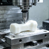
The CAM phase is where your digital design is translated into actionable instructions for the CNC machine. After importing your clean CAD file (e.g., a STEP or DXF), the CAM software becomes your virtual workshop. Here, you define every aspect of the physical machining process, from how the material is held down to the precise path the cutting tool will take. This step requires a blend of technical knowledge and practical experience to be done effectively.
The core of the CAM process is generating toolpaths. This involves several key decisions. First, you must select the correct cutting tool (e.g., a 1/4" flat end mill) from a tool library. Next, you define the 'feeds and speeds'—the feed rate (how fast the tool moves through the material) and the spindle speed (how fast the tool rotates). These settings are critical and vary based on the material being cut, the tool being used, and the machine's capabilities. Incorrect settings can lead to broken tools, poor surface finish, or damage to the machine.
Once tools and settings are defined, you apply machining strategies. For example, to cut out a shape, you might use a 'profile' or 'contour' toolpath that follows the outline. To hollow out an area, you would use a 'pocket' toolpath. As recommended by guides like one from Make Better Furniture, simulating the toolpaths within the CAM software is an essential final check. This simulation provides a visual preview of the entire machining job, allowing you to catch potential collisions, errors, or inefficient movements before any material is cut.
After the toolpaths are simulated and verified, the final step is 'post-processing'. The CAM software takes all the toolpath information and uses a specific post-processor file tailored to your CNC machine's controller (e.g., Mach3, GRBL, Fanuc). This converts the universal toolpath data into the specific G-code dialect that your machine understands. The resulting .nc or .gcode file is the finished product, ready to be loaded onto the CNC for execution. Before running the job with your actual material, it is always a good practice to run an 'air cut'—running the program with no material in place—to ensure the machine movements are exactly as expected.
Frequently Asked Questions
1. How to prepare files for a CNC machine?
Preparing files for a CNC machine is a step-by-step process. It starts with creating a precise 2D or 3D design in CAD software, ensuring the geometry is clean and designed for manufacturability. Next, you export the design to a CNC-friendly format like STEP for 3D or DXF for 2D. This file is then imported into CAM software to generate toolpaths, set tool parameters, and simulate the cutting process. Finally, the CAM program post-processes the toolpaths into a G-code file that the CNC machine can read and execute.
2. What file format is needed for CNC?
The best file format depends on the type of machining. For 3D CNC machining (milling and turning), STEP (.stp or .step) is the preferred industry standard because it preserves the full 3D geometry with high accuracy. IGES is another common 3D format. For 2D CNC machining (like laser, plasma, or router cutting), DXF is the most widely used format. While formats like STL are used for 3D printing, they should generally be avoided for precision CNC machining because they represent models as a mesh of triangles rather than true curves and surfaces.
-
Posted in
CAD, CAM, cnc machining, file preparation, G-Code


