
Essential Tool Length Offset Basics for Accurate CNC Machining
TL;DR
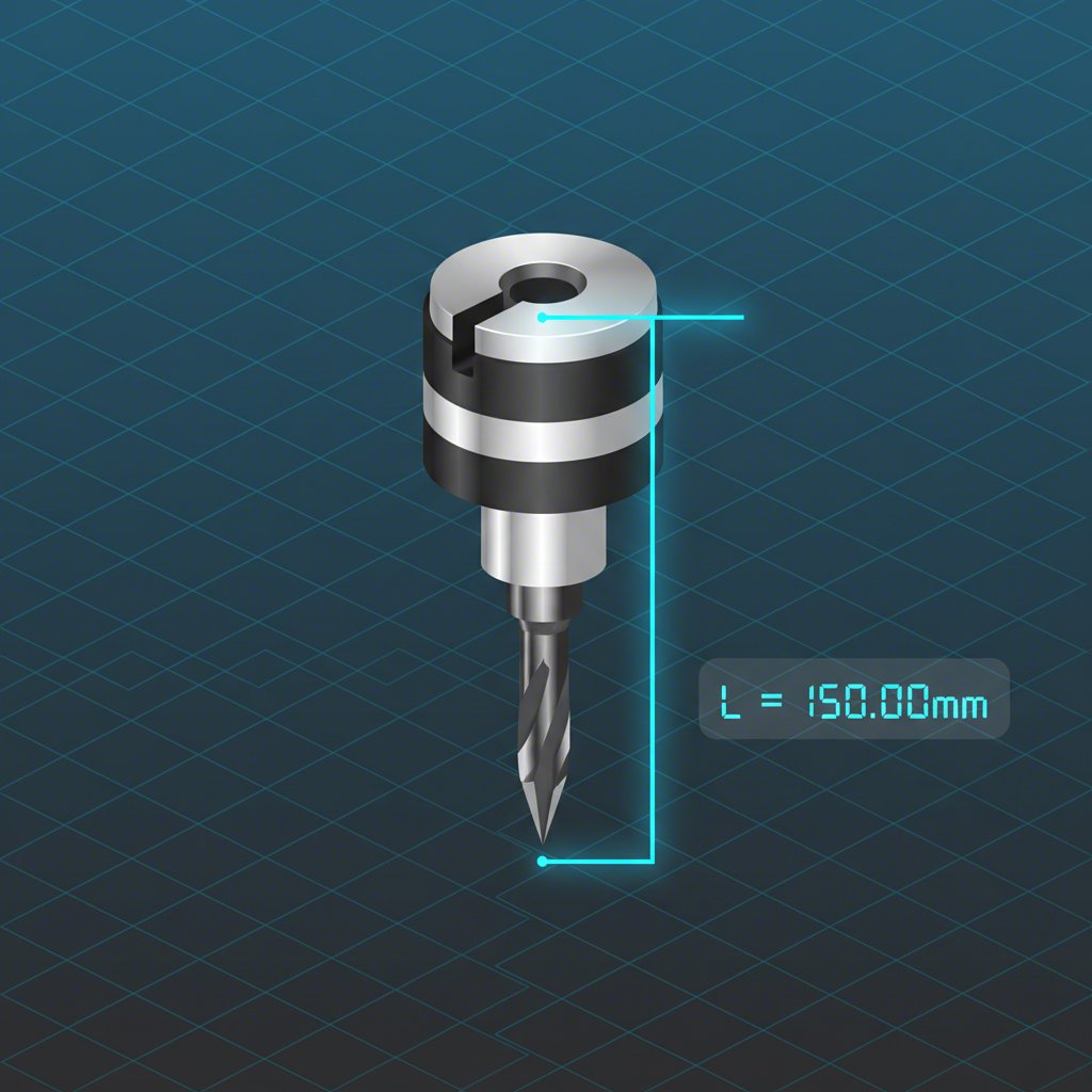
A tool length offset (TLO) is the precise distance measured from a known reference point on a CNC machine's spindle—typically the spindle nose or gauge line—to the very tip of the cutting tool. This critical value is essential for the machine's control system to accurately compensate for the varying lengths of different tools. Properly setting the TLO ensures the tool cuts at the correct depth specified in the program, which is fundamental for producing accurate parts and preventing costly machine crashes.
What Is a Tool Length Offset and Why Is It Critical?
In CNC machining, precision is everything. The machine's controller executes a program with thousands of coordinate points, but it only has one built-in, unchanging reference point on the Z-axis: the spindle nose. However, machinists use countless tools of different lengths, from short stub drills to long-reach end mills. A tool length offset is the crucial piece of information that bridges this gap. It tells the machine exactly how far the tip of the currently loaded tool extends from that spindle nose reference point.
Without this offset, the machine would attempt to move its spindle nose to the programmed cutting depth, which would almost certainly result in a catastrophic crash, damaging the tool, the workpiece, and potentially the machine itself. The TLO enables the machine to compensate for the tool's length, ensuring only the tool's cutting tip reaches the programmed coordinates. This allows for seamless tool changes within a single program, as the machine can automatically adjust for each tool's unique length.
It's common for beginners to confuse tool offsets with work offsets, but they serve distinct purposes. A tool offset defines the tool's geometry, while a work offset defines the part's location on the machine table. Getting them mixed up is a frequent source of error that leads to scrapped parts. Understanding the difference is a fundamental step toward becoming a proficient machinist.
| Concept | Purpose | What It Defines |
|---|---|---|
| Tool Length Offset (TLO) | To compensate for the length of each individual tool. | The distance from the spindle nose to the tool tip. |
| Work Offset (e.g., G54) | To locate the workpiece on the machine. | The distance from the machine's home position to the part's zero point (datum). |
Mastering tool length offsets is a non-negotiable skill for ensuring accuracy and repeatability. While individual practice is key, for projects demanding the highest precision with tight tolerances, leveraging professional expertise can be a significant advantage. For instance, services dedicated to precision manufacturing, such as XTJ CNC milling, rely on meticulously managed offset systems and advanced probing technology to deliver components that meet stringent quality standards.
Common Methods for Setting Tool Length Offsets
Machinists use several methods to measure and set tool length offsets, ranging from simple manual techniques to fully automated systems. The choice often depends on the available equipment, the required accuracy, and the production environment. Each method has its own set of advantages and disadvantages in terms of speed, precision, and cost.
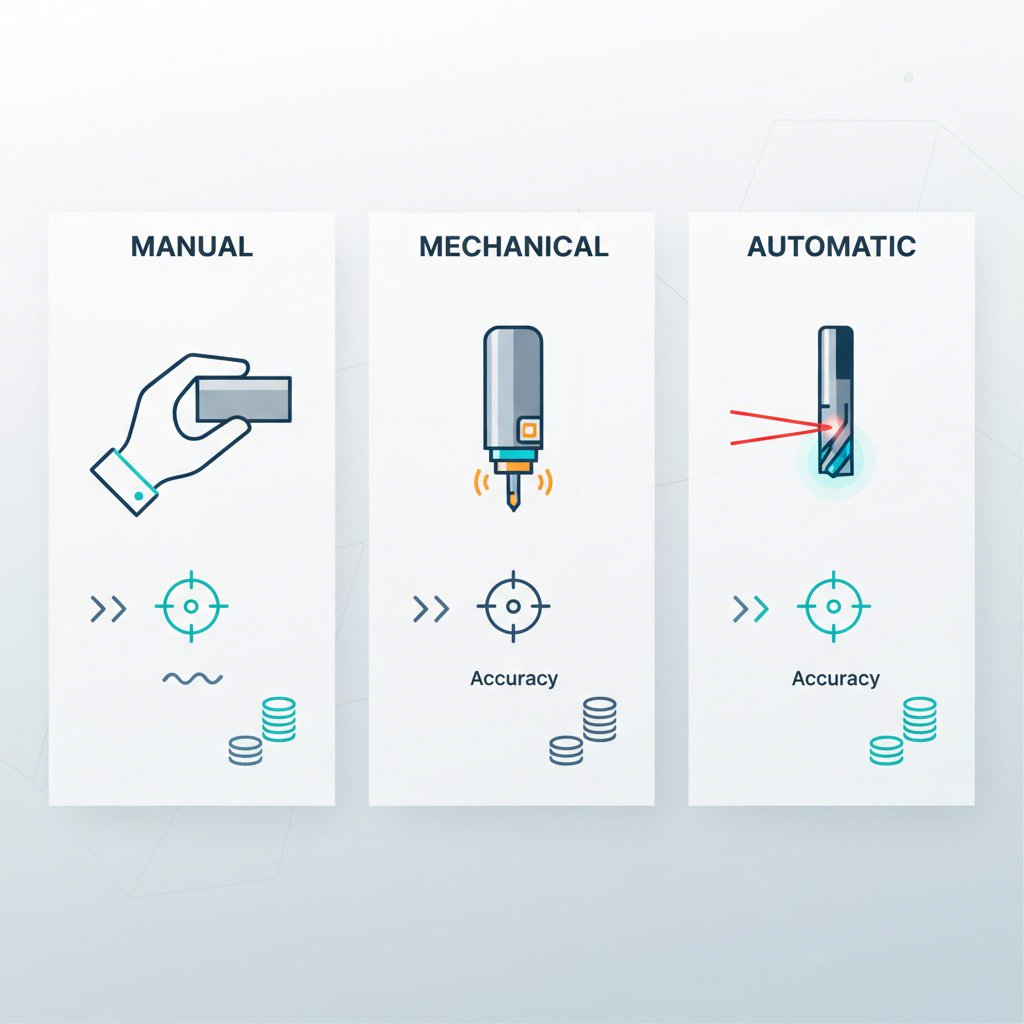
The most basic approach is manual setting. This can involve carefully jogging the tool down to touch the top of the workpiece (if it's a known, flat surface) or, more commonly, touching off on a precision ground block (like a 1-2-3 block) placed on the machine table or vise. While inexpensive, this method is slow and highly susceptible to operator error. A slight miscalculation or an unclean surface can easily lead to an incorrect offset value.
A more advanced and reliable method involves using a tool setter, which can be either mechanical or electronic. A mechanical or touch-probe setter features a surface that the tool is brought down to touch. When the tool makes contact, the probe triggers and records the position. Automatic setters, such as laser-based systems, offer the highest level of accuracy and speed. The tool is rotated through a laser beam, which measures its length and diameter without physical contact, automatically inputting the values into the machine's offset library. This process, detailed in resources from MHCC Pressbooks, minimizes human error and is ideal for high-production environments.
Here is a simplified step-by-step process for setting a tool manually using a 1-2-3 block on the machine table:
- Place a clean 1-2-3 block flat on the machine table, noting its exact height (e.g., 1.000 inch).
- Load the tool into the spindle.
- Carefully jog the tool down towards the block. Use a piece of paper or a feeler gauge between the tool tip and the block to avoid crashing.
- When you can no longer slide the paper freely, the tool is at the height of the block.
- Record the machine's Z-axis position from the display. This value is then used to calculate the tool length offset, often by subtracting the height of the 1-2-3 block.
- Enter this value into the correct offset register in the machine's controller.
| Method | Pros | Cons |
|---|---|---|
| Manual (Gage Block) | Low cost, can be done on any machine. | Slow, high risk of operator error, less accurate. |
| Mechanical Tool Setter | Good accuracy and repeatability, faster than manual. | Requires setup, potential for wear or damage to the probe. |
| Laser/Automatic Setter | Highest accuracy, fastest method, non-contact. | Expensive, requires a compatible machine. |
Regardless of the method used, diligence is key. Experts at Premium Parts emphasize that double-checking entered values and maintaining clean measurement surfaces are essential best practices for preventing costly mistakes stemming from incorrect tool offsets.
Positive vs. Negative Offsets and G-Code Application (G43 H)
Once a tool's length is measured, the value is stored in the CNC controller's offset library. To apply this value during a program, machinists use a specific G-code command: `G43`. This command activates tool length compensation, telling the machine to adjust its Z-axis position based on the length of the active tool. The `G43` command is always paired with an `H` code, which specifies which offset register to use (e.g., `H05` calls the value stored for tool 5).
A typical line of code to apply the offset looks like this:
G43 Z2.0 H05;
This command instructs the machine to: activate tool length compensation (`G43`), use the value from offset register 5 (`H05`), and then move the tool tip to a position 2.0 inches above the part's Z-zero (`Z2.0`). It is a critical safety practice to always activate the tool length offset on the first Z-axis move after a tool change, well above the part, to prevent the uncompensated tool from crashing.
There are two primary systems for managing tool length offsets: positive and negative. As explained in a detailed guide by Zero-Divide, the choice between them often depends on a shop's equipment and workflow. In a positive offset system, the TLO value is the actual measured length of the tool from the spindle's gauge line to the tool tip. This method is highly portable; a tool measured on an offline pre-setter can be moved between machines with the same offset value. It is the preferred system in automated environments.
In a negative offset system, the TLO value represents the distance from the tool tip (when at the machine's Z home position) down to the part's Z-zero. This method is simpler for beginners on a single machine, as the Z work offset is often set to zero. However, it is less flexible because the tool offset is tied to a specific part setup and is not transferable to other machines or jobs without re-measuring.
Understanding which system your machine or shop uses is fundamental. Positive offsets, measured from the machine's gauge line, are generally considered more robust and scalable, especially in shops with tool pre-setters and multiple machines. Negative offsets can be simpler for one-off jobs but lack the portability required for efficient production environments.
Frequently Asked Questions
1. What is the difference between a work offset and a tool offset?
A tool offset and a work offset are both crucial for CNC machining, but they define different things. A tool offset specifies the geometry of the cutting tool, primarily its length (Tool Length Offset) and sometimes its radius. It tells the machine how long the tool is. A work offset (e.g., G54, G55) tells the machine where the workpiece is located on the machine's table by defining the position of the part's zero point (datum) relative to the machine's home position.
2. What is the result of a wrong tool offset?
An incorrect tool length offset can have severe consequences. If the offset value makes the machine think the tool is shorter than it actually is, the machine will drive the tool too deep into the workpiece, potentially scrapping the part, breaking the tool, or even damaging the machine's spindle. Conversely, if the machine thinks the tool is longer than it is, it will cut air or machine too shallow, resulting in an inaccurate part with incorrect dimensions. In both cases, it leads to wasted time, material, and money.
-
Posted in
cnc machining, CNC programming, G-Code, manufacturing, Tool Length Offset


