
Precision vs. Cost: Understanding CNC Machining Tolerances

TL;DR
CNC machining tolerance is the acceptable range of variation in a part's dimensions from its ideal design. Because no manufacturing process can produce a perfectly exact part, tolerances define a permissible limit—often a standard of +/- 0.005 inches (0.13mm)—within which a component is considered functional and meets its form, fit, and function requirements. Tighter tolerances provide greater precision but significantly increase manufacturing costs and complexity.
What Are CNC Machining Tolerances?
In the world of precision manufacturing, achieving exact dimensions is a practical impossibility. CNC machining tolerances, also known as dimensional accuracy, refer to the permissible variance in the physical dimensions of a manufactured part compared to its design specifications. This concept is fundamental to ensuring the proper form, fit, and function of components, especially those intended for assembly. If a part is machined outside its specified tolerance, it may not connect correctly with other parts, leading to product failure.
The need for tolerances arises from the inherent variability in any manufacturing process. Factors like machine wear, tool deflection, material properties, and even ambient temperature can introduce minute deviations from the blueprint. Tolerances provide a realistic and acceptable range for these variations. This range is often called the "tolerance band," which is the difference between the maximum (upper limit) and minimum (lower limit) acceptable dimensions for a feature. A wider band signifies a "loose" tolerance, while a narrower band indicates a "tight" tolerance.
A widely accepted standard tolerance for CNC machined metal parts is +/- 0.005 inches (0.13mm), while for plastics, it's often +/- 0.010 inches due to their lower rigidity and higher thermal expansion. It's crucial for designers to understand the trade-off between precision and cost. While it might seem desirable to specify the tightest possible tolerances, doing so dramatically increases manufacturing costs. Achieving higher precision requires more advanced machinery, slower cutting speeds, specialized tooling, more rigorous inspection processes, and results in a higher scrap rate for parts that fall outside the narrow acceptable range. Therefore, the most effective design strategy is to apply tight tolerances only to critical features where they are absolutely necessary for function.
Key Types of Machining Tolerances
Designers use several methods to specify tolerances on engineering drawings, each suited for different functional requirements. Understanding these types is essential for clear communication between the designer and the machinist. The most common types include bilateral, unilateral, and limit tolerances, which are complemented by a more comprehensive system known as Geometric Dimensioning and Tolerancing (GD&T).
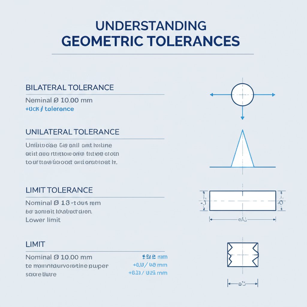
Bilateral tolerances permit variation in both positive and negative directions from the nominal or basic size. For example, a dimension of 25mm ±0.1mm means the final part can be anywhere between 24.9mm and 25.1mm. This is common for features where the deviation can be symmetrical without affecting function. Unilateral tolerances, on the other hand, allow variation in only one direction. A dimension specified as 25mm +0.2/-0.0mm indicates the part can be up to 25.2mm but no smaller than 25.0mm. This is critical for features like shafts that must fit into holes, where being oversized is unacceptable.
Limit tolerances directly state the upper and lower boundaries without a nominal size. Instead of 25mm ±0.1mm, a drawing might specify the dimension as 25.1 / 24.9. This method is straightforward and removes any ambiguity for the machinist. These dimensional tolerances are often depicted in a comparison table for clarity.
| Tolerance Type | Example Notation | Lower Limit | Upper Limit | Description |
|---|---|---|---|---|
| Bilateral | 25.0 mm ±0.1 mm | 24.9 mm | 25.1 mm | Variation is allowed in both positive and negative directions from the nominal size. |
| Unilateral | 25.0 mm +0.2/-0.0 mm | 25.0 mm | 25.2 mm | Variation is allowed in only one direction from the nominal size. |
| Limit | 25.1 / 24.9 | 24.9 mm | 25.1 mm | Directly states the maximum and minimum acceptable dimensions. |
While these cover size, modern manufacturing often requires control over shape, orientation, and location. This is where Geometric Dimensioning and Tolerancing (GD&T) comes in. GD&T is a comprehensive symbolic language used on engineering drawings to communicate complex requirements. It uses symbols to control features like flatness, perpendicularity, concentricity, and true position, providing far more detailed control than simple dimensional tolerances alone. According to information from Protolabs, GD&T ensures that not only the size but also the geometric relationships between features are maintained, which is critical for the performance of complex assemblies.
Understanding Standard Tolerances and Industry Charts (ISO 2768)
To simplify the design and manufacturing process, many machine shops and international standards organizations have established "standard" or "general" tolerances. If a designer does not specify a particular tolerance on a drawing, the machinist will apply a default shop standard, which is often +/- 0.005 in. (0.13mm) for metals. This practice streamlines production by providing a baseline level of precision without requiring explicit instruction for every single dimension.
A key international standard for general tolerances is ISO 2768. This standard is intended to simplify drawing specifications and is applied to parts made by metal removal or forming. As detailed by manufacturing service providers like 3ERP, ISO 2768 is divided into two parts: one for linear and angular dimensions (ISO 2768-1) and another for geometric tolerances (ISO 2768-2). ISO 2768-1 specifies four tolerance classes: fine (f), medium (m), coarse (c), and very coarse (v). The "medium" class is most commonly used as a default.
The standard provides a chart that correlates a part's nominal dimension with the permissible deviation for each class. For example, for a dimension between 6mm and 30mm, the permissible deviation under the "medium" class is ±0.2mm, whereas for the "fine" class, it is ±0.1mm. This systematic approach ensures consistency and avoids ambiguity.
Here is a simplified example of how ISO 2768-1 (medium class) might be represented:
| Nominal Dimension Range (mm) | Permissible Deviation (ISO 2768-m) |
|---|---|
| 0.5 up to 3 | ±0.1 mm |
| > 3 up to 6 | ±0.1 mm |
| > 6 up to 30 | ±0.2 mm |
| > 30 up to 120 | ±0.3 mm |
| > 120 up to 400 | ±0.5 mm |
Relying on standards like ISO 2768 is efficient for non-critical features. However, for features that require precise mating or alignment, designers must specify custom, tighter tolerances. When asked if 0.1mm is a good tolerance, the answer depends entirely on context. For a non-critical feature on a medium-sized part, ±0.1mm (a "fine" tolerance under ISO 2768) is quite precise and reasonable. For a high-precision bearing fit, it might be far too loose.
Factors That Influence Tolerances and Cost
The ability to achieve a specific tolerance—and the associated cost—is not arbitrary. It is a direct result of several interconnected factors, including material choice, machine capability, and part geometry. The most fundamental principle for any designer to remember is that tighter tolerances invariably lead to higher costs and longer manufacturing times. Understanding why this happens is key to designing cost-effective, manufacturable parts.
The cost increase stems from multiple sources. Achieving high precision may require more advanced and expensive CNC machines, slower machining speeds to minimize tool deflection, and specialized cutting tools. Furthermore, inspection becomes more time-consuming and may necessitate sophisticated equipment like Coordinate Measuring Machines (CMMs). The scrap rate also increases, as even minor deviations can cause a part to fall outside the narrow window of acceptability. This is why a tolerance of ±0.005 inches is often considered the threshold where costs begin to rise significantly.
Several key factors directly influence a machine's ability to hold a given tolerance:
- Material Type: The stability and machinability of the material are critical. Hard, stable metals like steel are generally easier to machine to tight tolerances than soft materials like plastics (e.g., Nylon, HDPE), which can flex or distort under the pressure of the cutting tool. Materials with high thermal expansion can also pose challenges as they change size during machining.
- Machine Capability and Condition: Not all CNC machines are created equal. The machine's age, rigidity, spindle accuracy, and overall condition directly impact its precision capabilities. A well-maintained, high-end 5-axis mill can hold tighter tolerances than an older, standard 3-axis machine.
- Part Geometry: Complex features, such as very thin walls, deep pockets, or small, intricate details, are more difficult to machine accurately. Thin walls can vibrate or deflect during cutting, making it hard to maintain dimensional consistency.
- Tool Wear: Cutting tools wear down over time, which can subtly alter part dimensions. Holding tight tolerances requires frequent tool changes and careful monitoring, adding to both time and cost.
For designers aiming to balance precision with budget, the key is strategic tolerancing. Instead of applying a single tight tolerance across an entire part, focus only on critical features—such as mating surfaces, bearing bores, and alignment pins. For projects requiring expert guidance on balancing these factors, turning to a specialized service can be highly beneficial. For instance, you can accelerate your product development with XTJ's comprehensive formative manufacturing services, which offer Design for Manufacturability (DFM) feedback to help optimize tolerances for both performance and cost.

Frequently Asked Questions About CNC Tolerances
1. What are the standard tolerances for CNC machining?
The most widely accepted standard tolerance for CNC machining is approximately +/- 0.005 inches (or about 0.13 mm) for metal parts. For plastic parts, the standard is typically looser, around +/- 0.010 inches, due to the material's tendency to flex and expand with temperature changes. Many machine shops will apply this standard if no specific tolerances are provided on the engineering drawing.
2. Is 0.005 inches considered a tight tolerance?
Yes, +/- 0.005 inches (0.13 mm) is generally considered the threshold where tight tolerance machining begins. While it is a standard offering at many shops, achieving tolerances tighter than this typically requires additional process controls, more advanced machinery, increased inspection, and slower cycle times, all of which contribute to a significant increase in manufacturing cost.
3. Is 0.1 mm a good tolerance?
Whether ±0.1 mm is a good tolerance is entirely dependent on the application. For many general mechanical parts, it is considered a reasonably precise or "fine" tolerance (as defined by the ISO 2768-f standard) and is achievable without excessive cost. However, for high-precision applications such as aerospace components, medical devices, or interference fits like bearings, a tolerance of ±0.1 mm would likely be too loose to ensure proper function.
-
Posted in
cnc machining, engineering tolerance, GD&T, ISO 2768, manufacturing design


