
Aluminium Prototype Mold Or Steel? Choose The Right Tooling
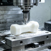
Aluminium Prototype Mold
When you’re racing to validate a new part design, waiting months for steel tooling just isn’t an option. That’s where the aluminium prototype mold comes in—offering a faster, more cost-effective pathway to real injection-molded parts. But what exactly is an aluminum mold, and how does it fit into the landscape of prototype tooling, bridge tooling, and rapid tooling? Let’s break it down step by step so you can make confident, informed decisions for your next project.
What is an Aluminium Prototype Mold?
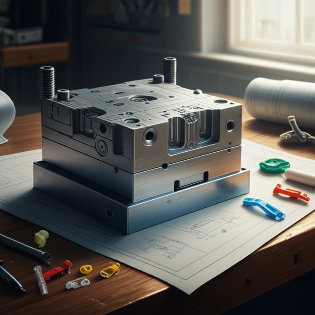
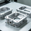
An aluminium prototype mold is a specially machined tool, typically made from high-grade aluminum alloys, used to produce plastic parts in short or moderate runs—often before full-scale production begins. Unlike hard steel molds, which are engineered for millions of cycles, aluminum molds are designed for speed, flexibility, and affordability. They’re a core part of prototype tooling, enabling teams to test part geometry, material choices, and manufacturing feasibility without the heavy investment or long lead times of conventional steel tools.
When Aluminum Beats Steel for Early Runs
Sounds complex? Imagine you need 500-5,000 test parts to validate a design or tweak features based on user feedback. Here’s where aluminum molds for injection molding shine. Their excellent machinability means cavities can be CNC milled rapidly—often in days, not weeks. This agility is ideal for:
- Prototype Tooling: Quick-turn tools for design validation and functional testing.
- Bridge Tooling: Interim molds that "bridge" the gap between prototyping and full-scale production.
- Rapid Tooling: Fast, flexible solutions for low- to mid-volume runs, risk mitigation, or market pilots.
Why choose aluminum over steel for these scenarios? It’s all about matching the tool to your business objectives—whether that’s time-to-market, cost control, or reducing the risk of investing in a design that might change.
- Speed: Aluminum molds can be produced 2-3x faster than steel molds.
- Cost: Tooling costs are typically 50-75% lower for aluminum than steel.
- Durability: Aluminum molds are best for hundreds to tens of thousands of shots, while steel is suited for millions.
| Tool Material | Lead Time (Business Days) | Typical Shot Life | Relative Cost |
|---|---|---|---|
| Aluminum | 15-25 | 1,000–100,000+ | Low |
| Steel | 35-60 | 100,000–1,000,000+ | High |
The biggest advantage of an aluminium prototype mold? You can get your first molded parts in weeks, not months—accelerating learning and reducing project risk.
How Prototype Tooling De-risks Production
Choosing an aluminum mold isn’t just about speed or price—it’s about smarter product development. By enabling quick design iterations and early testing, you’ll notice fewer surprises when you commit to production tooling. This approach reduces costly rework, shortens time-to-market, and helps control investment risk. However, keep in mind: resin selection, part geometry, and your expected shot count should always guide your tooling choice. For complex, high-volume, or highly abrasive applications, steel may still be the better long-term fit.
In summary, an aluminium prototype mold is a strategic tool for engineers and sourcing teams looking to move fast, learn early, and minimize risk—making it a cornerstone of modern product development and bridge tooling strategies.
DFM Guidelines for Aluminum Tooling
When you’re evaluating an aluminium prototype mold, the difference between a smooth, cost-effective run and a headache of delays often comes down to Design for Manufacturability (DFM). Sounds complex? It doesn’t have to be. By focusing on a few key design elements, you can dramatically improve tool life, ensure stable part ejection, and avoid costly surprises—whether you’re working with aluminum tooling for rapid prototyping or low-volume production.
Drafts, Walls, and Radii for Aluminium Tooling
Imagine trying to eject a sticky ice cube from a tray. If the sides are too straight or the shape is too sharp, it’s a struggle. The same principle applies to injection mold tooling—especially with aluminum. Here’s what you need to watch for:
- Draft Angles: Add enough draft (typically 1-2 degrees or more) to all vertical faces. This reduces friction and prevents parts from sticking, especially important since aluminum is softer and more prone to galling than steel.
- Wall Thickness: Keep walls consistent—avoid abrupt transitions. Target 1.0–3.0 mm for most plastics, but always check your resin’s specs.
- Radii and Fillets: Generous internal radii (0.5 mm or larger) reduce stress, improve flow, and minimize tool wear.
| Feature Type | DFM Guidance |
|---|---|
| Ribs | Keep rib thickness ≤ 60% of nominal wall, add fillets at base |
| Bosses | Connect to walls with gussets, add draft, avoid isolated bosses |
| Living Hinges | Not recommended for aluminum tooling due to fatigue risk |
| Holes/Slots | Maintain spacing ≥ wall thickness, add radii to reduce stress |
| Undercuts | Design for simple lifters or slides; minimize complexity for aluminum |
Gate, Runner, and Vent Choices that Reduce Iterations
Getting resin to flow evenly in your aluminium prototype mold is crucial for both part quality and tool longevity. Aluminum’s high thermal conductivity supports rapid cooling, but you may need to tweak your design to prevent hotspots or warpage. Here’s a quick DFM essentials checklist before you send out your RFQ:
- Consistent wall thickness
- Minimum 1-2° draft on all core/cavity surfaces
- Generous radii and fillets at corners
- Well-supported ribs and bosses
- Optimized hole and slot spacing
- Robust gating and runner design
- Ample venting at end-of-fill and thick sections
For gating, use larger gates and runners when possible—aluminum molds cool quickly, so you want to ensure complete cavity fill before freeze-off. Vents should be deep and wide enough to let air escape, but not so big as to cause flash. These small tweaks can cut down the number of mold revisions needed and keep your injection molding tooling project on track.
Early DFM decisions—like adding draft and consistent wall thickness—are the single biggest factor in ensuring reliable part ejection and reducing tool damage.
Tolerances and Surface Finish Expectations
How tight do you need your tolerances? Aluminum tooling can achieve excellent precision, but expect slightly looser tolerances compared to hardened steel—think ±0.1 mm as a general rule for most features, but always specify critical-to-function dimensions clearly. For cosmetic surfaces, note which faces need high polish or texture versus those that are purely functional. This helps your supplier focus effort (and cost) where it matters most.
Don’t forget: early DFM reviews—ideally before quoting—can help you spot features that will drive up machining or EDM time. Small geometry changes, like adding fillets or relaxing tolerances, can reduce lead time and lower costs for your tooling for injection moulding project.
By following these aluminum DFM guidelines, you’ll set the stage for a rapid, reliable prototype run—while minimizing surprises during mold trials. Next, let’s look at the step-by-step manufacturing workflow, from CNC machining through to final finishing.
Manufacturing Workflow
Ever wondered how an aluminium prototype mold goes from a digital concept to a real-world tool ready for aluminum injection molds or injection mold prototype runs? The journey is a blend of smart design choices and advanced machining—each step impacting speed, cost, and final part quality. Let’s break down the typical manufacturing workflow and highlight what makes aluminium injection molding unique.
CNC Strategies that Shorten Lead Time
When you need parts fast, high-speed CNC machining is the backbone of tool and mold making for aluminium. Aluminum’s excellent machinability means cavities, cores, and inserts are milled rapidly and with impressive detail. But what does the process actually look like?
- CAD Design: Engineers create a detailed 3D model of the mold, optimizing for cooling, ejection, and part geometry.
- CAM Programming: Toolpaths are generated, balancing roughing (for fast material removal) with finishing passes for critical surfaces.
- CNC Milling: High-speed machines cut the aluminum blocks, using sharp cutters and optimized feeds to minimize burrs and tool wear.
- EDM (if needed): For deep ribs, sharp corners, or delicate features, Electrical Discharge Machining comes into play.
- Surface Finishing: The mold receives its specified texture—machined, bead-blasted, or chemically etched—plus any required coatings.
- T1 Sample Runs: The mold is assembled and tested with resin, producing first-article parts for evaluation and final tweaks.
By leveraging modern 3+2 or 5-axis CNC machines, many features that once required EDM can now be milled directly, slashing lead times for cnc injection mold builds. Toolpath optimization and smart cutter selection further reduce the need for secondary finishing or hand polishing—getting you to T1 samples faster.
When to Use EDM for Feature Integrity
Still, not every detail is CNC-friendly. Imagine you’re designing a prototype injection moulding tool with deep, thin ribs or ultra-sharp internal corners. Here’s where EDM (Electrical Discharge Machining) shines:
| Process | Speed | Detail/Geometry | Achievable Radii | Typical Finish |
|---|---|---|---|---|
| CNC Milling | Fast | Most features, some limits on depth/sharpness | ≥ cutter diameter (usually ≥0.5 mm) | Machined, may need polishing |
| EDM | Slower | Deep, sharp, or delicate features | Extremely small, sharp corners possible | Consistent, matte (no machining marks) |
EDM is often reserved for areas where CNC can’t reach or where feature fidelity is critical. However, it’s slower and requires electrode planning—so minimizing EDM use can help keep your project on schedule and budget.
Surface Finish and Coating Options for Aluminium
The final look and performance of your aluminium injection molding tool depend heavily on finishing choices. Here’s a quick rundown of common options and what they mean for your mold:
- Machined Finish: Fastest, but may show tool marks. Suitable for non-cosmetic or functional surfaces.
- Bead Blast: Creates a uniform matte texture, hiding minor imperfections and improving release.
- Chemical Etch: Adds texture for grip or aesthetics; can help with demolding.
- Anodizing (Type II or Hardcoat): Increases wear and corrosion resistance, prolonging tool life.
- Plating (Nickel, Chrome): Adds a thin, durable surface—ideal for abrasive or high-volume runs.
- Powder Coating: Durable and colorful, but less common for mold cavities due to thickness.
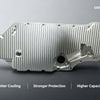
Choosing the right coating or finish isn’t just about looks—it can dramatically affect tool longevity, part release, and thermal performance. For example, anodizing helps aluminum resist wear and corrosion, while bead blasting can make demolding easier. Always specify which surfaces are critical for polish or texture in your RFQ to avoid surprises.
The right blend of CNC, EDM, and finishing choices is what transforms a digital design into a high-performing, cost-effective aluminum prototype mold.
Curious about the finer details of aluminum prototype manufacturing? Check out this in-depth guide on aluminum prototype processes to see real-world examples and tips for success.
With the mold built and finished, the next step is to select the right resin and dial in your molding process—ensuring your prototype injection mould delivers the quality and repeatability your project demands.
Getting the Most from Your Aluminium Prototype Mold
Ever wondered if your resin choice could make or break your aluminium prototype mold project? The truth is, aluminum molds are far more versatile than many engineers think—capable of handling a wide spectrum of thermoplastics, including high-heat and abrasive grades. But to achieve reliable, cost-effective results, it pays to understand how different resins interact with soft tooling, and how to tweak your process for long tool life and consistent parts.
Resin Families and Aluminium Tool Suitability
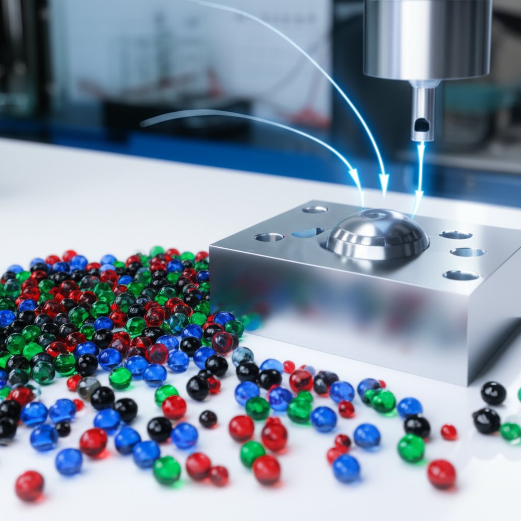
When you’re picking a resin for aluminum injection molding or prototype injection molding, you’ll want to consider more than just end-use performance. Aluminum’s excellent thermal conductivity helps most resins flow and cool evenly, but certain families require extra attention. Here’s a quick reference for common resin types and how they behave in aluminum molds:
| Resin Group | Abrasion Risk | Temperature Suitability | Corrosion/Other Notes | Demolding Considerations |
|---|---|---|---|---|
| Unfilled (ABS, PP, PC, Nylon) | Low | Excellent | Minimal risk | Easy, especially with good draft |
| High-Temp (Ultem, Vectra) | Low-Moderate | Good (cartridge heaters may be needed) | Monitor for thermal expansion | May need additional draft for shrinkage |
| Glass/Mineral-Filled | High | Good (use hardcoat or steel inserts) | Accelerated wear if uncoated | Release can be tougher—use coatings |
| PVC, Flame Retardant, Corrosive | Low | Good | Aluminum is naturally corrosion resistant | Standard demold practices |
As you can see, most mainstream thermoplastics run beautifully in aluminum prototype molds. Even abrasive, glass-filled, or high-temperature resins are possible—just specify hardcoating or steel inserts for high-wear zones and monitor tool condition over time.
Managing Heat, Shear, and Abrasion Risks
Sounds complex? It’s more about smart process tweaks than major overhauls. Aluminum’s superior heat transfer means faster cooling, but you’ll want to watch for:
- Hot Spots: Less likely, but can still occur with thick sections or slow-filling resins.
- Shear Stress: Even heating reduces shear, minimizing splay and burning—especially helpful with clear or high-viscosity materials.
- Abrasion: Glass- or mineral-filled resins can wear down uncoated aluminum. Use anodizing, plating, or steel inserts at gates, runners, and shutoffs for longer mold life.
For soft tooling injection molding projects, these simple upgrades can extend tool life from thousands to hundreds of thousands of shots—even with challenging materials.
Gating and Venting Adjustments for Stable Shots
Getting great results from your prototype injection mould isn’t just about resin choice—it’s also about how you get the resin in and the air out. Aluminum’s fast heat transfer means gates and runners may freeze off sooner, so consider slightly larger gates or multi-gate layouts for complete fill. Venting is also crucial: well-placed, deep (but narrow) vents help eliminate burn marks, voids, and short shots, especially with high-viscosity or filled resins.
- Mold temperature (start cooler, then adjust up as needed)
- Pack/hold pressure (optimize to avoid sink and flash)
- Cooling time (aluminum usually allows shorter cycles)
- Screw speed (slower for filled or high-heat resins)
Testing these parameters during T1–T2 trials helps you dial in part quality and maximize tool life—without over-investing in unnecessary upgrades.
Balancing fast cycle times with careful tool protection is key: a few seconds saved per shot can mean thousands more parts before your aluminum tool needs maintenance or repair.
By understanding resin compatibility and making small, strategic adjustments to your process, you’ll get the most out of your aluminium prototype mold—whether you’re running a handful of prototype injection molds for testing or scaling up to bridge production. Up next, we’ll explore how partnering with the right rapid prototyping expert can further accelerate your tooling outcomes and minimize risk.
Partnering for Faster Aluminium Tooling Outcomes
When does it make sense to bring in a specialized partner for your aluminium prototype mold? Imagine you’re facing a tight deadline, complex geometry, or need functional aluminium prototypes in days, not weeks. In these scenarios, partnering with a rapid prototyping expert can be the difference between a smooth launch and a costly delay. But how do you know when to engage outside help, and what should you prepare to get the most out of the collaboration?
When to Engage a Rapid Prototyping Partner
If you’re working on rapid prototyping injection molding or need quick-turn aluminum prototype tooling, consider reaching out to a specialist when:
- You need to iterate designs quickly and validate multiple concepts in parallel.
- The part geometry is complex, requiring advanced CNC, die casting, or multi-cavity tooling expertise.
- Your in-house resources are constrained or lack experience with aluminum prototype mold builds.
- You want access to multidisciplinary capabilities—like DFM feedback, material selection, and secondary processes—all under one roof.
- Risk mitigation is critical, and you can’t afford costly rework or missed deadlines.
Specialized providers not only accelerate delivery, but also help you avoid common pitfalls by offering design-for-manufacturability (DFM) reviews, up-to-date process knowledge, and robust project management.
What to Include in Your RFQ Package
Ready to request a quote? A clear, detailed RFQ (Request for Quote) is your ticket to fast, accurate pricing and fewer surprises. Here’s a checklist of what to include:
- 3D CAD File (STEP/IGES): The foundation for manufacturing and DFM review.
- 2D Drawings with GD&T: Annotate critical dimensions, tolerances, and surface finishes.
- Resin Specification: Include grade, color, and any special requirements.
- Target Volumes: State expected prototype and bridge production quantities.
- Cosmetic and Functional Notes: Highlight areas needing high polish, texture, or functional testing.
Providing these details upfront empowers your partner to flag manufacturability risks, suggest design tweaks, and optimize your rapid prototype tooling for cost and cycle time.
- Initial DFM review and risk assessment
- Design iteration and approval
- Tooling kickoff and weekly progress updates
- T1 sample delivery and feedback loop
- Final approval and bridge production ramp-up
Early DFM collaboration is the fastest way to spot design risks, reduce tooling changes, and ensure your aluminum prototype delivers on time.
How Multidisciplinary Capabilities Reduce Risk
Why settle for a one-dimensional supplier when you can tap into a full suite of tooling and injection molding services? The most effective partners offer CNC machining, injection molding, die casting, and even finishing—all in-house. This approach streamlines communication, shortens lead times, and ensures your aluminium prototyping project benefits from holistic DFM input at every stage.
For example, a provider like Rapid Prototyping Services brings together advanced CNC, molding, and die casting under one roof, with ISO 9001:2015 certified quality controls. Their engineers offer complimentary DFM feedback, help select from over 50 materials (including 6061 and 7075 aluminum), and support both metal and plastic aluminium prototypes from concept through production. This kind of multidisciplinary support is invaluable for reducing technical risk—and for ensuring your aluminum prototype meets both schedule and performance targets.
By partnering early and leveraging a team with broad capabilities, you gain speed, quality, and confidence—giving your project a measurable edge as you move toward production. Next, let’s explore how to plan for tool life, maintenance, and refurbishment to maximize the value of your investment.
Tool Life Planning, Maintenance, and Refurbishment for Aluminium Prototype Molds
When you invest in an aluminium prototype mold, the real value comes from maximizing its useful life while keeping maintenance and downtime to a minimum. But how do you plan for tool longevity, and what maintenance routines actually make a difference? Let’s break down the essential strategies for keeping your mold tooling running smoothly, so you can deliver reliable prototype molds and avoid costly surprises.
Estimating Tool Life without Overcommitting
Ever wondered how many shots you can really expect from your aluminum tooling? The answer depends on several factors—resin abrasiveness, part complexity, process stability, and whether you’ve added surface coatings or steel inserts in high-wear zones. For example, filled resins like glass-filled nylon will wear down uncoated aluminum much faster than unfilled ABS or polypropylene. Likewise, intricate geometries with deep ribs or lots of side actions put more stress on the mold.
| Scenario | Typical Shot Life | Notes |
|---|---|---|
| Unfilled resin, simple geometry | Up to 100,000+ | With good maintenance and moderate volumes |
| Filled resin, complex geometry | 10,000–50,000 | Expect more frequent inspections, possible insert wear |
| Coated aluminum for molds | 100,000–1,000,000+ | With Nibore or hardcoat and careful process control |
Keep in mind: excessive injection pressures or temperatures can quickly shorten tool life, even with coatings. Documenting your process parameters and tracking shot counts is the best way to correlate wear with actual production conditions.
Maintenance and Inspection Checkpoints
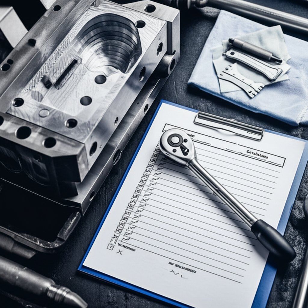
Sounds tedious? Not if you have a simple, repeatable preventive maintenance (PM) routine. Regular care doesn’t just extend the life of your tooling molds—it protects part quality and keeps your schedule on track. Here’s a PM checklist you can use after every run or before storage:
- Disassemble and thoroughly clean all mold surfaces
- Clear vents and runners of any residue or buildup
- Inspect for wear, galling, or surface pitting—especially at gates and shutoffs
- Check alignment of cores, cavities, and any side actions
- Lubricate moving parts and apply mold release as needed
- Store in a controlled environment (dry, stable temperature)
For high-wear applications, inspect coated areas for signs of breakdown. If you notice parting line flash, sticking, or cosmetic defects, it’s a signal to review your PM logs and investigate possible root causes—sometimes a minor adjustment or quick polish is all that’s needed.
Refurbishment and Insert Strategies
Even the best-maintained aluminum for molds will eventually show signs of wear. The good news? Many issues can be remedied without a full rebuild, thanks to smart insert strategies and repair options:
- Repair: Minor erosion or galling can often be addressed by polishing or re-coating affected surfaces. Small weld repairs are possible, but inserts are usually preferred.
- Refurbish: For more significant wear—such as at gates, shutoffs, or deep features—replaceable steel or aluminum inserts can be swapped out without scrapping the entire mold. This is especially valuable if you anticipated revision-prone areas during the design phase.
- Rebuild: If wear is widespread, or if a major design change is needed, a new core or cavity may be the most cost-effective path. This is also the time to consider upgrading to bridge or production tooling if volumes are increasing.
Protecting high-wear features with replaceable inserts is the single best way to extend mold life and reduce long-term costs.
Designing for maintainability up front—such as using inserts in anticipated revision zones or high-abrasion areas—can save you both money and downtime over the life of your prototype molds. And remember, documentation is your friend: keep shot logs, resin lot records, and parameter sheets to help diagnose any shifts in tool performance.
By following these practical maintenance and refurbishment strategies, you’ll get more cycles, better part quality, and greater ROI from every aluminium prototype mold investment. Next, we’ll compare aluminum with alternative tooling approaches to help you make the right choice for your next project.
Choosing Between Aluminium and Alternative Tooling
Aluminium vs Soft Steel vs Cast Aluminum
When you’re selecting a mold tool for your next project, the options can feel overwhelming. Should you stick with an aluminium prototype mold, upgrade to soft steel, or try cast aluminum? Each route has unique strengths and trade-offs. Let’s break down the differences so you can make a confident, informed decision.
| Tooling Type | Lead Time | Detail Fidelity | Finish Potential | Expected Durability | Cost Tier |
|---|---|---|---|---|---|
| Aluminium Prototype Mold | Fastest | Good (best for simple to moderate complexity) | Good, but may show wear sooner | Low–Medium (hundreds to 100,000 shots) | Low |
| Soft Steel (e.g., P20) | Moderate | Excellent (supports tight tolerances and complex shapes) | Excellent, maintains finish longer | Medium–High (100,000 to 1,000,000+ shots) | Medium |
| Cast Aluminum | Moderate | Fair (less precise, best for large or simple parts) | Fair, more porosity risk | Low–Medium | Low–Medium |
Aluminium tooling is the go-to choice for rapid prototyping and short runs thanks to its quick turnaround and lower upfront cost (Slide Products). Soft steel, like P20, is ideal when you need tighter tolerances, higher part counts, or plan to run abrasive or high-temperature resins. Cast aluminum is less common for precision injection molding but can be a practical option for larger, simple geometries where ultra-high accuracy isn’t required.
Where Additive or Hybrid Tooling Fits
What about additive manufacturing and hybrid approaches? If you’re dealing with highly complex cooling channels or want to experiment with conformal-cooling inserts, 3D printing can be integrated into your injection mould tools strategy. These hybrid tools combine printed inserts with traditional aluminum or steel frames, offering new design freedoms and faster cooling for intricate parts. However, additive tooling is typically best for short runs or as bridge tooling—cost and durability may not match traditional CNC’d aluminum moulds for high-volume production.
- Simple, low-volume parts: Choose aluminium for speed and cost savings.
- Complex, high-tolerance parts: Opt for soft steel to ensure detail and longevity.
- Large, non-critical parts: Cast aluminum may suffice if tight tolerances aren’t needed.
- Parts needing advanced cooling or design flexibility: Consider hybrid or additive tooling for rapid iteration.
- Abrasive or high-temp resins: Steel or hybrid with steel inserts for durability.
Decision Factors that Matter Most
Imagine you’re racing to market with a new product. Do you need parts in days, or is long-term durability your top priority? Here are the main factors to consider when choosing between aluminium tooling and its alternatives:
- Geometry complexity: More complex shapes favor steel or hybrid tools.
- Resin behavior: Abrasive or high-temp materials favor steel; most general-purpose resins are fine with aluminum.
- Finish requirements: High-cosmetic or optical parts may require steel for consistent quality.
- Shot expectations: For hundreds to tens of thousands, aluminum is ideal; for hundreds of thousands to millions, steel is a must.
- Schedule constraints: Tight timelines favor aluminum or hybrid solutions.
The best mold tool is the one that aligns with your volume, timeline, and part requirements—choose aluminum for speed, steel for endurance, and hybrids for innovation.
By mapping your project’s needs to these attributes, you’ll select the right aluminum mould or alternative—balancing speed, cost, and risk. Next, we’ll wrap up with a practical cost and scheduling framework to help you plan your next tooling investment with confidence.
Procurement Checklist for Aluminium Prototype Molds
When you’re sourcing an aluminium prototype mold, the difference between a smooth project and costly setbacks often comes down to the procurement process. Sounds complex? It doesn’t have to be. By following a structured, vendor-neutral approach, you can ensure your tooling for injection molding project stays on track, meets your quality standards, and delivers the ROI you expect. Here’s a practical playbook to help you compare suppliers, clarify expectations, and validate results—without missing a beat.
What to Include in Your RFQ and Drawings
Imagine sending out a request for quote (RFQ) and getting back apples-to-apples proposals—no confusion, no hidden gaps. That’s the goal. Your RFQ package should be clear, detailed, and standardized. Here’s an effective structure to follow, inspired by best practices from industry leaders:
- 3D CAD File (STEP/IGES): The digital foundation for mold design and DFM checks.
- 2D Drawings with GD&T: Annotate all critical dimensions, tolerances, and surface finishes for your injection mould tool.
- Resin Specification: State the exact grade, color, and any special additives or requirements.
- Estimated Volumes: Provide expected prototype, bridge, and production quantities.
- Quality Expectations: Specify inspection standards, sample sizes, and any required certifications.
- Special Notes: Highlight cosmetic zones, functional surfaces, and any areas open to design feedback or cost optimization.
Providing this information upfront allows suppliers to quote accurately and flag any potential risks or ambiguities before manufacturing begins.
Supplier Capability and Quality Evidence
How do you know if a supplier is up to the challenge? Beyond price, it’s critical to assess their technical strength, experience, and quality systems. Consider sending a short questionnaire with your RFQ. Here are key areas to cover:
- Machinery: What CNC, EDM, and finishing machines are in-house?
- Materials: Can they source and process your specified aluminum grade and resin?
- Metrology: What inspection tools and CMMs are used for dimensional checks?
- Certifications: Do they hold ISO, ASTM, or other relevant quality certifications?
- Experience: Can they provide examples of prior mould tool manufacture with similar tolerances or resins?
- Process Documentation: Will they share sample process sheets, inspection reports, and mold trial logs?
| Capability Area | What to Request |
|---|---|
| Machinery | List of CNC/EDM equipment, finishing capabilities |
| Materials | Material certificates, sourcing details |
| Metrology | Inspection tools, CMM reports, calibration records |
| Certifications | ISO/ASTM/industry certificates |
| Experience | Case studies, sample parts, references |
| Process Control | Sample process sheets, inspection logs |
This approach helps you vet suppliers for their ability to deliver reliable proto tooling—not just low prices.
Post-Build Validation and Handover
Once your aluminium prototype mold is built, the job isn’t finished—validation is essential. You’ll want to see clear, documented evidence that the tool meets all agreed specifications before moving to production. Here’s a step-by-step outline for post-build success:
- T1 Sample Review: Receive first-article parts and full dimensional inspection report.
- Capability Runs: Confirm the mold can repeatedly produce parts within tolerance.
- Process Documentation: Request finalized process sheets, shot logs, and maintenance instructions.
- Final Handover: Ensure you receive all CAD/CAM data, inspection records, and certificates for your injection mould tool.
Clear documentation and standardized validation steps are your best defense against ambiguity, rework, and missed expectations.
By following this procurement checklist, you’ll minimize surprises, build a transparent supplier relationship, and ensure your next aluminium prototype mold project delivers on every front. Ready to move forward? Next, we’ll show you how to estimate costs, plan your schedule, and map out the ROI for your tooling investment.

Cost, ROI, and Scheduling
Trying to make sense of aluminum injection mold cost and project timelines? You’re not alone. Whether you’re budgeting for your first injection molding prototype or comparing options for prototype parts manufacturing, understanding the real cost drivers and scheduling milestones is critical for making smart, confident decisions. Let’s break down a step-by-step, practical approach to help you map out your investment, minimize risk, and plan for fast, reliable delivery.
Estimating Cost and Break-Even Without Guesswork
Sticker shock from a tooling quote can make anyone pause. But focusing on upfront price alone can be misleading. The real question is: How does your investment in an aluminium prototype mold pay off over the life of your project?
- Gather Quotes: Request detailed quotes for each tooling route—aluminum prototype, soft steel, and any hybrid or additive options. Make sure each includes mold cost, expected shot life, and estimated lead time.
- Estimate Per-Part Cost: For each route, calculate per-part cost by adding material, machine time, and amortized tooling cost (mold cost divided by expected production volume).
- Model Volumes and Change Risk: Consider your realistic part quantity, expected design changes, and whether you’ll need to revise the tool. Aluminum molds excel for low-to-mid volumes and rapid iterations.
- Compare Total Landed Cost: Add up tooling, per-part, and any secondary costs (like finishing or trial runs). Use the table below to visualize the differences.
- Choose a Path: Select the tooling solution that aligns with your schedule, budget, and risk tolerance. Remember, the lowest upfront cost isn’t always the best value—especially if changes or delays are likely.
| Tooling Route | Tooling Cost Range | Expected Shots | Lead Time | Best For |
|---|---|---|---|---|
| Aluminium Prototype Mold | $3,000–$10,000 | 1,000–100,000+ | 2–4 weeks | Rapid prototyping, bridge runs, design changes |
| Soft Steel Tool | $8,000–$30,000+ | 100,000–1,000,000+ | 4–10 weeks | High-volume, tight tolerance, abrasive materials |
| Additive/Hybrid Tooling | $5,000–$20,000+ | 500–10,000 | 1–3 weeks | Complex geometry, conformal cooling, fast iteration |
Keep in mind: injection molded prototypes often justify aluminum tooling, especially when speed and flexibility are top priorities. For high-volume production or highly abrasive resins, steel tools may offer better long-term ROI.
Compressing your tooling schedule can unlock market opportunities—delays in first shots often cost more than a higher tooling quote.
Lead-Time Planning from RFQ to First Shots
Wondering how long it really takes to go from quote to usable parts? Here’s a practical timeline based on industry best practices and real-world project data:
- RFQ and DFM Review: 1–2 weeks for supplier feedback, part design checks, and tool design approval.
- Tool Fabrication: 2–4 weeks for aluminum prototype molds (longer for steel or multi-cavity tools).
- T0 Trial (First Shots): 1 week to validate basic mold function and identify initial issues.
- T1/T2 Iterations: 1–3 weeks for modifications, validation samples, and final approval.
In total, expect 4–8 weeks for a typical aluminum prototype mold from RFQ to production-ready T2 samples, depending on complexity and responsiveness. Proactive communication and fast feedback can shave weeks off this schedule.
Bringing It Together with a Trusted Partner
Imagine having a partner who not only delivers your tooling fast, but also helps you optimize design, material selection, and process parameters for the best ROI. That’s where working with an experienced, multidisciplinary team pays off. For example, a provider like XTJ Rapid Prototyping Services offers quick-turn DFM feedback, supports both metal and plastic prototypes, and provides access to a wide material portfolio—including popular aluminum alloys. Their ISO-certified processes and collaborative approach help you de-risk your project and accelerate time-to-market.
By following this structured approach to cost analysis and scheduling, you’ll have the confidence to choose the right tooling route for your aluminium prototype mold project—balancing speed, flexibility, and ROI. Ready to turn your design into reality? With the right partner and a clear plan, you can move from concept to injection molded prototypes faster than ever before.
Frequently Asked Questions About Aluminium Prototype Molds
1. How long do aluminum injection molds last?
Aluminum injection molds typically last between 3,000 and 100,000 cycles, depending on the resin type, part geometry, and whether protective coatings or steel inserts are used. Proper maintenance and choosing suitable materials can significantly extend the tool's lifespan, especially for prototype or bridge production runs.
2. What is a prototype mold and how is aluminum used?
A prototype mold is a tool designed to quickly produce sample or low-volume parts for testing and validation before mass production. Aluminum is often chosen for prototype molds because it is easy to machine, allows fast turnaround, and offers cost savings compared to steel, making it ideal for design iterations and early-stage product development.
3. Are aluminum molds better than steel for prototyping?
Aluminum molds are preferred for prototyping because they can be manufactured much faster and at a lower cost than steel molds. They are excellent for short runs, design changes, and rapid testing, while steel molds are more suitable for high-volume, long-life production due to their durability.
4. What resins are compatible with aluminum prototype molds?
Most common thermoplastics, including ABS, PP, PC, and unfilled nylons, are compatible with aluminum prototype molds. For abrasive or high-temperature resins, using hard coatings or steel inserts helps maintain tool life and part quality. Early resin trials with conservative settings are recommended to optimize results.
5. When should I consider partnering with a rapid prototyping service for aluminum molds?
Partnering with a rapid prototyping service is ideal when you need fast design iterations, complex part geometries, or access to multidisciplinary manufacturing capabilities like CNC, injection molding, and die casting. These partners offer DFM feedback, material selection support, and ISO-certified quality control, reducing technical risk and speeding up development.
-
Posted in
aluminium prototype mold, aluminum tooling, DFM guidelines, injection mold prototyping, rapid prototyping