
Rapid Prototyping Aluminium: 9 Essential Points That Slash Risk
Rapid prototyping aluminium fundamentals
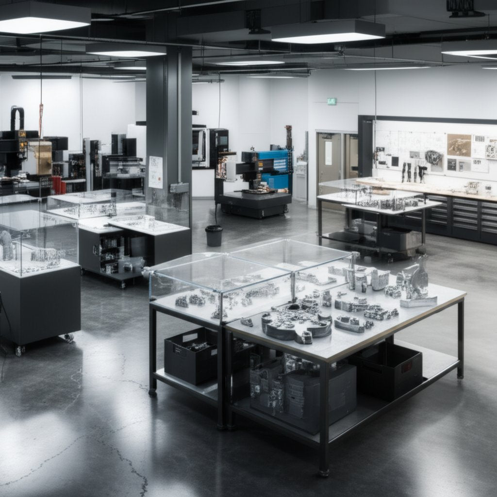
Ever wondered why so many engineers turn to aluminium when speed, precision, and real-world testing matter most? If you’re new to aluminium prototyping or simply want to make smarter process choices, this chapter lays the groundwork for risk-free, rapid iteration. Let’s break down what rapid prototyping aluminium means, where it shines, and how to align your process to your project’s unique needs.
What rapid prototyping aluminium means for engineers
At its core, rapid prototyping aluminium is the practice of quickly producing physical, functional prototypes or components from aluminium alloys. It’s a cornerstone of rapid prototyping manufacturing—a discipline that empowers teams to test, refine, and validate designs before moving to full-scale production. But what is rapid prototyping in this context? It’s not just speed for speed’s sake: it’s about building parts that closely mimic final product performance, enabling everything from fit checks to load testing and regulatory validation.
Why aluminium? You’ll notice its reputation for:
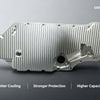
- Exceptional strength-to-weight ratio: Aluminium weighs about one-third as much as steel, yet certain alloys (like 7075) offer impressive mechanical strength, making it ideal for weight-sensitive applications in aerospace and automotive fields [XTJ CNC Blog].
- Superior machinability: Aluminium can be cut, milled, and formed much faster than steel—significantly faster than most steels, often reducing machining time by over 50% depending on the specific application and parameters—resulting in quicker turnaround and lower labor costs for metal prototyping.
- Corrosion resistance: Alloys like 6061 naturally resist rust and oxidation, and can be further protected through anodizing—a major plus for prototypes exposed to moisture or chemicals.
- High recyclability: Aluminium scraps and chips are easily recycled, making your prototyping process both cost-effective and environmentally responsible. Recycling aluminium consumes only around 5% to 8% of the energy needed for primary production.
- Thermal and electrical conductivity: Useful for heat sinks, enclosures, and electronic prototypes where temperature management or conductivity is essential.
When aluminium beats plastics and steel in early builds
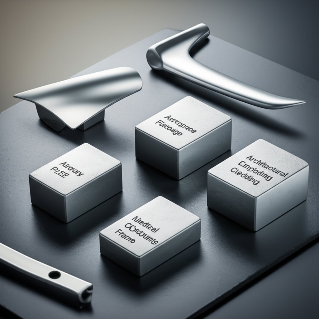
Choosing aluminium for manufacturing prototypes isn’t always a given. Imagine you need a prototype that not only looks the part but can withstand real mechanical loads, thermal cycling, or repeated assembly. Here’s where aluminium outperforms plastics (which may lack strength or heat resistance) and even steel (which adds unnecessary weight or cost in many applications). For functional tests, fixtures, or pilot builds where the prototype must endure real-world stresses, aluminium delivers the right blend of toughness and agility.
- Better than plastics for structural, load-bearing, or high-temperature parts
- Lighter than steel while still offering high fatigue strength and dimensional stability
- More sustainable via recycling and lower energy consumption
However, if your prototype is purely cosmetic, ultra-low cost, or needs extreme hardness, plastics or steels may still have a place.
Process choice signals that save time and rework
How do you actually make aluminium prototypes? There’s no one-size-fits-all answer. The main processes include:
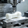
- CNC machining: Subtractive process for high-precision, complex geometries, and tight tolerances. Refer to ISO 2768 or your supplier’s specs for typical machining tolerances.
- Sheet metal forming: Best for enclosures, brackets, and thin-walled parts with bends or folds. Quick, cost-effective for simple geometries.
- Metal additive manufacturing (AM): Technologies like selective laser melting (SLM) or direct metal laser sintering (DMLS) enable intricate internal features and rapid design changes. For terminology, see the ISO/ASTM 52900 series.
- Casting: Sand, investment, or die casting for larger runs or parts with complex internal cavities. For acceptance criteria, review ASTM aluminium casting standards.
To align process with project needs, ask:
- Is the prototype for functional, mechanical, or thermal testing? (Lean toward CNC or metal AM.)
- How complex is the geometry? (AM for complexity; CNC or sheet metal for simpler forms.)
- What’s your timeline and budget? (Sheet metal and CNC for speed; casting for volume.)
- Will you need to iterate quickly? (CNC and AM excel for rapid changes.)
For every project, match your aluminium prototyping process to the function, timeline, and budget—don’t default to what’s familiar. The right choice slashes risk and maximizes learning before production.
In summary, rapid prototyping aluminium is about leveraging the unique properties of aluminium and the right manufacturing method to deliver reliable, test-ready prototypes—fast. By understanding these fundamentals, you’ll be better equipped to choose the right path for your next rapid prototyping metal parts challenge.
Aluminium alloy selection made simple
Choosing the right aluminium alloy for your cnc aluminum prototype can feel overwhelming. Should you go for high strength, easy machining, or top corrosion resistance? Let’s break it down into practical, engineer-friendly terms—so your next aluminum prototype delivers exactly what you need, without surprises.
Picking between 6061 and 7075 for functional testing
Imagine you’re building prototype parts that need to balance strength, machinability, and cost. The two most common choices—6061 and 7075—each bring unique advantages:
| Alloy | Machinability | Strength | Corrosion Resistance | Weldability | Fatigue Behavior | Typical Use Cases | Notes on Temper |
|---|---|---|---|---|---|---|---|
| 6061 | Excellent | Good | Excellent | Excellent | Good | Automotive, marine, brackets, fixtures, general CNC prototyping | T6/T651 for improved strength and dimensional stability |
| 7075 | Good | Excellent | Fair | Poor | Excellent | Aerospace, high-performance sporting goods, load-bearing prototype aluminum | T6 for peak strength; more brittle, less weldable |
6061 stands out for its ease of cnc prototype machining and broad compatibility with finishing processes. It’s the all-rounder for most cnc aluminium prototyping projects, especially if you require welding or corrosion resistance. In contrast, 7075 is the go-to for maximum strength and fatigue resistance—think aerospace or performance-critical applications—but it can be trickier to machine and is not recommended if welding is required [Kormax].
When to choose 5052 or 5083 for formed sheet parts
What if your aluminum prototype needs to be bent, folded, or shaped? Alloys like 5052 and 5083 are the favorites for cnc prototyping service involving sheet metal work:
| Alloy | Formability | Strength | Corrosion Resistance | Weldability | Fatigue Behavior | Typical Use Cases | Notes on Temper |
|---|---|---|---|---|---|---|---|
| 5052 | Excellent | Moderate | Excellent | Excellent | Good | Enclosures, panels, marine parts, brackets | H32/H34 for balance of strength and formability |
| 5083 | Good | High | Excellent | Excellent | Excellent | Pressure vessels, marine, transport, heavy-duty formed parts | H111/H116 for marine and structural use |
5052 is your workhorse for easy bending and moderate strength, while 5083 offers higher strength and top-tier corrosion resistance—ideal for demanding marine or transport prototypes.
Heat treatment choices that influence prototype behavior
Ever noticed codes like T6 or T651 after an alloy number? These temper designations tell you how the alloy was treated—and they matter. For example, 6061-T6 is solution heat treated and artificially aged for extra strength, while T651 adds stress relief, reducing distortion after cnc prototype machining. Picking the right temper boosts both performance and dimensional accuracy. For sheet alloys, H32 (strain hardened and stabilized) balances formability with strength. Always consult your supplier’s datasheet or standards for the best match.
| Temper | Process | Effect on Properties | Typical Prototype Use |
|---|---|---|---|
| T6 | Solution heat treated & artificially aged | High strength, good dimensional stability | Load-bearing, precision CNC parts |
| T651 | T6 plus stress relief | Reduces warping after machining | Intricate CNC prototypes, large parts |
| H32/H34 | Strain hardened & stabilized | Balance of strength and formability | Sheet metal prototypes, enclosures |
- For cost-sensitive projects, 6061 or 5052 are typically more affordable and widely available.
- If finishing (like anodizing) is critical, check alloy compatibility with your supplier.
- When tight tolerances matter, specify temper (e.g., T651) to minimize post-machining distortion.
- For prototype aluminum exposed to harsh environments, prioritize corrosion resistance (5052, 5083).
Understanding alloy and temper choices helps you get the most out of your cnc prototyping service. Next, we’ll look at how to compare rapid prototyping processes so you can match your material to the right manufacturing route—saving both time and money.
Process comparison for aluminium prototypes
When you’re staring at a fresh CAD model and a tight deadline, which rapid prototyping process should you choose for your aluminium part? Sounds complex? It doesn’t have to be. Let’s break down the most common manufacturing routes—CNC machining, metal additive manufacturing (AM), sheet metal forming, and casting—so you can match each to your project’s needs, budget, and timeline.
Which process best matches your geometry?
Imagine you’re tasked with building a lightweight, load-bearing bracket, a thin-walled enclosure, or a part with intricate internal channels. Each process brings unique strengths to the table. Here’s how the main options stack up for rapid prototyping metal parts:
| Process | Design Freedom | Min. Feature Size | Typical Tolerance | Surface Finish (Ra) | Material State/Temper | Lead Time | Scalability | Best For |
|---|---|---|---|---|---|---|---|---|
| CNC Machining | High (but limited by tool access) | ~0.5 mm | Tight (±0.05 mm typical) | Good (1.6–3.2 μm) | Wide alloy/temper choice | Fast (2–7 days) | Easy pilot scaling | Functional prototypes, fixtures, high-precision rapid cnc prototyping |
| Metal AM (SLM/DMLS) | Very high (complex internals, lattices) | ~0.3 mm | Moderate (±0.1–0.2 mm typical) | Fair (5–15 μm, post-process improves) | Limited alloy/temper (often as-built) | Fast (3–10 days) | Low–mid volume, hybrid builds | Intricate geometries, internal channels, rapid prototyping parts |
| Sheet Metal Forming | Moderate (2D bends, folds) | ~1.0 mm (sheet thickness) | Moderate (±0.2–0.5 mm typical) | Good (1.6–3.2 μm, varies by finish) | 5052, 5083, other ductile alloys | Very fast (1–5 days) | Easy for low–medium volume | Enclosures, brackets, rapid sheet metal prototyping |
| Casting (Sand, Investment, Die) | High (complex cavities, thick/thin walls) | ~1.5–2.0 mm | Broad (±0.3–0.8 mm typical) | Varies (5–25 μm, often needs post-finish) | Alloy/temper depends on process | Longer (2–4 weeks for tooling, 1–2 weeks for parts) | Best for high-volume pilot/production | Prototype aluminum casting, complex shapes, production intent |
Surface finish and tolerance expectations by process
Not all processes deliver the same look or precision. CNC machining and sheet metal rapid prototyping typically offer smoother surfaces and tighter tolerances right out of the machine. Metal AM and casting may require secondary finishing—like bead blasting or machining—to meet cosmetic or fit requirements. Always check your supplier’s capability sheet or refer to standards (e.g., ISO/ASTM 52900 for AM, ASTM for casting, ISO 2768 for machining) for acceptance criteria.
Scaling from prototype to pilot with minimal redesign
Planning for production? Here’s where process choice can make or break your timeline. CNC machining and sheet metal forming are ideal for quick iterations and pilot runs, allowing fast changes without new tooling. Metal AM shines for one-offs and highly complex parts, but may need design tweaks for cost-effective production. Casting (especially die casting) is the go-to for scaling—but requires upfront investment in molds and, often, slight design adjustments for draft angles and wall thickness.
- Choose CNC machining prototyping for tight tolerances and broad alloy selection.
- Pick metal AM for internal channels, lattice structures, or when you need to iterate rapidly on complex shapes.
- Use sheet metal forming for fast, cost-effective enclosures, brackets, and panels.
- Opt for prototype aluminum casting when you’re ready to simulate production or need complex cavities at higher volumes.
Matching your prototype’s geometry, function, and timeline to the right process is the fastest way to reduce rework and get reliable results—don’t default to one-size-fits-all thinking.
Want a deeper dive into the details and real-world examples of these processes? Check out this comprehensive guide: What Are the Processes in Aluminum Prototypes?
Next, we’ll explore design-for-manufacturability tips to help you avoid costly do-overs and nail your prototype the first time.
Design for manufacturability that prevents do-overs
Ever had a prototype that looked perfect in CAD but failed in the shop? Or found yourself trapped in a cycle of tweaks and rework? That’s where smart Design for Manufacturability (DFM) steps in—especially when working with rapid prototyping aluminium. Let’s break down practical DFM rules for each process so you can avoid costly surprises and keep your project moving forward.
DFM rules for CNC and thin-wall aluminium
When it comes to prototype machining and prototype cnc machining, thoughtful design choices can make or break your timeline and budget. Here’s what to focus on for cnc machined prototypes:
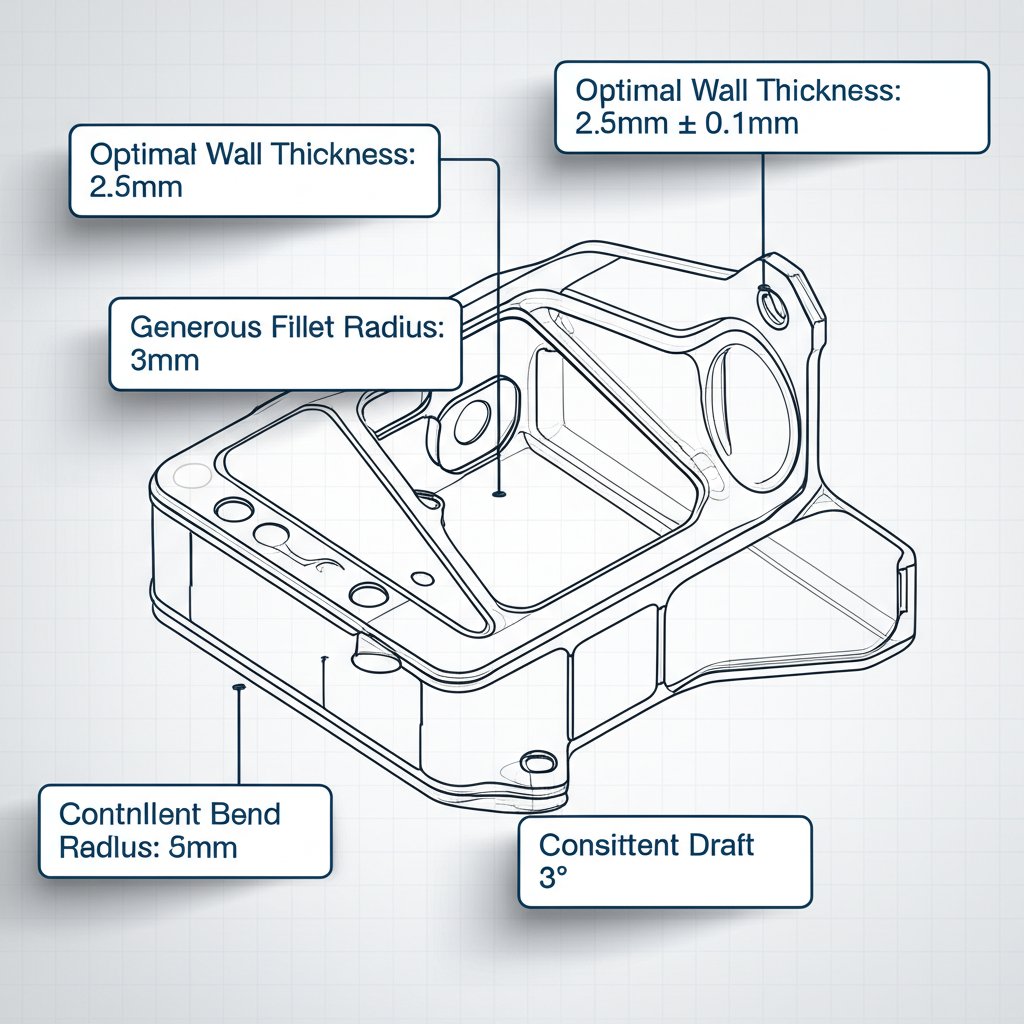
- Wall thickness: Keep walls a minimum of 1.0–1.5 mm thick for aluminium. Thinner walls increase risk of chatter, distortion, and higher costs.
- Fillets and inside corners: Add generous radii (≥1 mm) to internal corners. Sharp corners require special tools and slow down rapid prototype machining.
- Tool access: Avoid deep, narrow pockets or undercuts. Design features so standard tools can reach all surfaces without extra setups.
- Tolerances: Only tighten tolerances where function demands. Overly tight specs drive up cost and risk rework.
- Thread standards: Use standard thread sizes and depths. For aluminium, coarse threads are often more robust.
- Datum strategy: Dimension from functional datums to ensure consistency in inspection and assembly.
AM build orientation and support strategies that work
For metal additive manufacturing (AM), such as SLM or DMLS, DFM is all about printability and post-processing:
- Build orientation: Orient parts to minimize overhangs and reduce support material. This lowers post-processing time and surface blemishes.
- Supports: Design self-supporting angles (>45°) when possible. Plan for easy removal of supports in inaccessible areas.
- Lattice and thin features: Be cautious with lattice structures and thin walls; verify minimum printable size with your supplier.
- Post-heat treatment: Specify stress-relief heat treatment post-build to reduce warping and improve mechanical properties.
- Surface finish: Expect to machine or bead blast critical surfaces for tight tolerance or cosmetic needs.
Draft, fillet, and wall guidance for cast and formed parts
Designing for casting or prototype sheet metal fabrication comes with its own set of DFM rules:
- Draft angles (casting): Add 1–3° draft to vertical walls for easy mold release. Check with your foundry for alloy-specific recommendations.
- Uniform wall thickness (casting): Aim for consistent wall thickness to prevent porosity and shrinkage defects.
- Fillets (casting and forming): Use generous radii at internal corners to reduce stress concentrations and improve material flow.
- Gating and risers (casting): Let your foundry handle gating and riser placement, but flag areas prone to porosity for extra attention.
- Bend radii (sheet metal): Set bend radius ≥ material thickness for aluminium to avoid cracking. For 5052-H32, a radius equal to or greater than the material thickness is a good rule of thumb.
- K-factor and reliefs (sheet metal): Use standard K-factors for bend calculations and add reliefs at bends to prevent tearing.
- Hole spacing (sheet metal): Keep holes at least 1.5× material thickness from edges and bends.
Dimension from functional datums and keep tolerances as loose as function allows. Over-specifying leads to higher costs and more rework.
Lastly, always annotate critical-to-quality dimensions and surfaces in your drawings. This aligns inspection methods and prevents costly misunderstandings during cnc machining prototype or rapid cnc builds.
By applying these DFM strategies, you’ll prevent the most common do-overs in rapid prototyping aluminium. Next, we’ll show you how to evaluate vendors to ensure your prototypes arrive right the first time—and on schedule.
What to look for in prototype manufacturing companies
When you’re ready to turn your aluminium prototype design into reality, how do you pick the right partner among a sea of prototype manufacturers and prototyping companies? The stakes are high—choose well, and you get reliable parts, honest feedback, and a smooth path to production. Choose poorly, and you risk delays, costly rework, or a prototype that doesn’t reflect your intent. Let’s break down a practical, criteria-driven approach to evaluating rapid prototyping services for your next project.
How to evaluate rapid prototyping companies
Imagine you’re comparing a shortlist of rapid prototyping companies. What separates the top-tier from the rest? Look beyond glossy websites and focus on these core factors:
- Process breadth: Do they offer CNC machining, metal additive manufacturing (AM), sheet metal forming, casting, or even injection molding for hybrid builds?
- Material and temper coverage: Can they source and process common aluminium alloys (6061, 7075, 5052, 5083) and deliver the right tempers for your application?
- DFM (Design for Manufacturability) feedback: Will they review your files and suggest improvements to reduce risk and cost before cutting metal?
- Certifications and quality systems: Are they ISO 9001:2015 certified or do they have equivalent controls in place?
- Metrology and inspection: What in-house inspection capabilities do they offer—CMM, FAI, or detailed inspection reports?
- Lead time and responsiveness: How quickly can they turn around quotes, samples, and production runs?
- Finishing and secondary processes: Can they provide anodizing, bead blasting, or other finishes in-house or via trusted partners?
- Transparency and sample access: Are they willing to share sample reports or references (without breaching customer confidentiality)?
| Provider | Process Breadth | Aluminium Alloy Range | DFM Feedback | Certifications | Lead Time (Prototypes) | Finishing Options | Quality Checks |
|---|---|---|---|---|---|---|---|
| XTJ Rapid Prototyping Services | CNC, AM, Die Casting, Injection Molding | 50+ materials incl. 6061, 7075, 5052, 5083 | Complimentary, expert DFM review | ISO 9001:2015 | Fast (as quick as 2–7 days) | Anodizing, bead blasting, custom | FAI, CMM, material certs |
| HLH Prototypes | CNC, 3D Printing, Casting, Sheet Metal | Common grades (6061, 7075, plastics) | Engineering and design support | ISO certified, eco-friendly practices | Varies by process (rapid options) | Standard, some custom | Quality and accuracy benchmarks |
| Jiga Marketplace | CNC, AM, Injection Molding, Sheet Metal | Wide network, metals and plastics | Expert feedback pre-order | Vetted suppliers, escrow for security | Competitive (multiple bids) | Based on supplier network | Transparency, inspection on request |
Quality systems and inspection that matter
Not all prototype manufacturing companies approach quality the same way. Look for those who can demonstrate robust systems—think ISO certifications, traceable inspection reports, and clear acceptance criteria. Ask for:
- Sample inspection reports (with sensitive data redacted)
- References for similar aluminium prototyping projects
- Details on in-house vs. outsourced finishing and inspection
Remember, a good prototype manufacturer is transparent and proactive about sharing their process and quality controls without violating customer confidentiality.
Balancing speed, cost, and risk
It’s tempting to pick the fastest or cheapest provider—but for metal prototyping services, that can backfire if you sacrifice quality or miss a critical DFM review. Instead, weigh:
- How well the provider’s process matches your prototype’s geometry and function
- Responsiveness to questions and design changes
- Willingness to collaborate on risk reduction (e.g., suggesting design tweaks or alternative alloys)
- Ability to scale from prototype to production without starting over
"The right prototyping partner is more than a supplier—they’re a risk-reduction ally who helps you avoid costly mistakes and accelerates your path to market."
Before you commit, request a sample report or reference project, and clarify your expectations for DFM feedback, inspection, and turnaround. This approach ensures your rapid prototyping aluminium journey is both efficient and low-risk—setting you up for success as you move into failure mitigation and process refinement in the next phase.
Failure modes and proven mitigations
Ever seen a promising aluminium prototype scrapped due to warping, cracks, or surface flaws? It’s more common than you think—and preventable with the right know-how. Let’s break down the most frequent failure modes in rapid prototyping aluminium, from cnc rapid prototyping to casting and metal AM, and show you how to spot and fix them early. Imagine saving days or weeks by catching issues before they derail your schedule or budget.
Recognizing root causes before they scrap parts
Each rapid prototyping process for aluminium comes with its own set of pitfalls. Here’s what to watch for:
-
CNC machining defects (subtractive):
- Chatter and vibration—especially on thin walls, causing ripples or dimensional inaccuracy.
- Burrs—sharp edges left on small features, leading to assembly issues or safety hazards.
- Residual stress distortion—warping or twisting after machining, particularly in large or slender parts.
- Tool build-up—aluminium flakes adhering to the cutting edge, dulling tools and degrading finish.
-
Metal additive manufacturing (AM) issues:
- Lack-of-fusion—incomplete melting, creating weak, porous zones.
- Keyholing—over-melting, causing voids or surface craters.
- Surface roughness—layer lines or powder adhesion, requiring extra finishing.
- Anisotropy—directional mechanical properties, making parts weaker across build layers.
-
Casting challenges:
- Porosity—gas bubbles or shrinkage voids within the part.
- Cold shuts—incomplete fusion where metal fronts meet, leading to cracks.
- Misruns—metal failing to fill the mold, resulting in incomplete features.
-
Sheet metal forming risks:
- Springback—parts bending back after forming, missing target angles.
- Cracking—at tight bends or sharp corners, especially in less ductile alloys.
Design and process tweaks that reduce risk fast
How do you stop these issues before they start? Here are practical, proven mitigations for each process—drawn from real-world metal prototype manufacturing experience:
-
CNC rapid prototyping:
- Increase wall thickness or add ribs to support thin features and minimize chatter.
- Specify generous fillets in internal corners to distribute stress and ease machining.
- Use step-down toolpaths and sharp, coated cutting tools to improve chip evacuation and reduce tool build-up.
- Employ proper fixturing to prevent workpiece movement and distortion.
- Consider post-machining stress relief (e.g., heat treatment) for large or complex parts.
-
Rapid prototyping cnc machining (AM):
- Optimize build orientation to minimize overhangs and reduce support structures.
- Work with your supplier to adjust laser parameters and scan strategies for better fusion.
- Specify post-build heat treatments or hot isostatic pressing (HIP) to increase density and reduce porosity.
- Plan for secondary machining or bead blasting to achieve desired surface finish.
-
Rapid metal prototyping (Casting):
- Design with uniform wall thickness to avoid shrinkage porosity and misruns.
- Incorporate adequate draft angles and fillets for smoother mold release and reduced stress concentrations.
- Flag critical areas for supplier review—advanced foundries can use simulation to predict and address porosity or cold shuts.
- Consider non-destructive testing (NDT) for high-integrity or safety-critical parts.
-
Sheet metal rapid prototyping:
- Specify minimum bend radii (at least equal to material thickness) to prevent cracking.
- Use relief cuts at bends and maintain adequate hole spacing from edges.
- Collaborate with your supplier to adjust tooling and forming sequence for consistent results.
Stiffen while you thin: add ribs to support thin walls during machining. The right design tweak now prevents scrap later.
Inspection choices to validate critical features
Even with smart design and process controls, inspection is your last line of defense. For high-value prototype machining services, consider:
- First Article Inspection (FAI) for all critical dimensions and features.
- Coordinate Measuring Machine (CMM) checks for tight-tolerance or complex geometries.
- Non-destructive testing (X-ray, dye penetrant) for cast or AM parts where internal defects matter.
When in doubt, consult your supplier’s standards or request their recommended acceptance criteria—especially for porosity in castings or density in AM builds. This proactive approach ensures your rapid prototyping machining project delivers on both performance and reliability.
By understanding and addressing these failure modes up front, you’ll slash risk, reduce scrap, and keep your aluminium prototypes moving from concept to validation—fast. Next, we’ll explore how the right finishing strategies can further boost quality and protect your investment.
Finishing strategies for aluminium prototypes
When your aluminium prototype comes off the machine, it’s rarely ready for showtime—or for the real-world testing that aluminium castings and prototype fabrication demand. So, what’s next? The right finishing and post-processing steps can dramatically boost appearance, corrosion resistance, and even dimensional accuracy. Let’s break down the most common finishing paths and how they impact your rapid prototyping aluminium workflow.
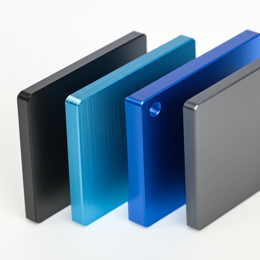
Surface finishes that balance looks and function
Think about the end-use of your prototype. Does it need a uniform matte look for demos, a brushed or polished finish for aesthetics, or a rugged, corrosion-resistant surface for functional testing? Here are the main finishing options you’ll encounter for prototype sheet metal parts and rapid sheet metal builds:
| Finish Type | Purpose | Impact on Dimensions | Corrosion Resistance | Lead Time Impact |
|---|---|---|---|---|
| As-Machined | Baseline finish, no extra cost | None | Low | Fastest |
| Bead Blasting | Uniform matte/satin look, hides tool marks | Minimal (removes slight material) | Low | +1–2 days |
| Brushed | Directional texture, improved scratch resistance | Minimal | Low | +1–2 days |
| Polished/Bright Dipping | High-gloss, mirror-like finish for appearance models | Minimal (removes surface layer) | Low | +2–3 days |
| Anodizing (Type II/III) | Corrosion/wear resistance, color options | Surface growth (typically 0.005–0.025 mm per side) | High | +2–5 days |
| Chem Film/Conversion Coating | Conductivity, moderate corrosion protection | Negligible | Moderate | +1–2 days |
| Powder Coating | Decorative, thick protective layer | Adds 0.05–0.15 mm | High | +2–4 days |
| Electroplating | Improved wear, conductivity, or aesthetics (e.g., nickel, chrome) | Adds thin layer (varies by process) | High (depends on deposit) | +3–7 days |
Anodizing and conversion coatings tradeoffs
For most aluminum die cast prototypes and high-performance aluminum casting projects, anodizing is the gold standard for durability and corrosion resistance. But did you know there are different types? Type II (sulfuric acid) is common for cosmetic and moderate-wear parts, offering vibrant color options. Type III (hardcoat) is thicker, tougher, and best for sliding or high-wear surfaces, though it can slightly reduce fatigue life and requires careful dimensional planning. Conversion coatings (like chem film/Alodine) are ideal when electrical conductivity is needed or for quick, cost-effective corrosion protection, but they’re not as robust as anodized layers. Always check your application’s requirements and consult standards such as MIL-PRF-8625 for anodizing specs.
Finishing plans that protect tolerances
Worried about losing your hard-won tolerances? Finishing can add or remove material—sometimes enough to push features out of spec. Here’s how to stay ahead:
- Plan masking for threads, tight fits, or functional surfaces before finishing.
- Allow stock for dimensional changes from anodizing (growth on all sides) or powder coating (layer thickness).
- Break sharp edges (edge break specs) to improve coating adhesion and prevent chipping.
- Request sample chips or coupons for finish approval before full production.
"A great finish starts with a great plan: specify finishes and masking early, and always allow for dimensional changes—especially on critical features."
- Protect threads and mating surfaces with masking or post-process cleaning.
- Specify edge breaks (e.g., 0.2 mm) for better finish durability.
- Approve finish samples before committing to a full run.
By understanding the finishing landscape, you’ll ensure your aluminium prototypes look as good as they perform—whether they’re destined for aluminium castings, prototype sheet metal parts, or complex aluminum die cast prototypes. Next up: how to streamline your procurement and RFQ process for rapid, risk-free iteration.
Procurement workflow and RFQ template
When you’re ready to move from CAD to a tangible aluminium prototype, the right procurement workflow can make all the difference. Sounds complex? It doesn’t have to be. By following a clear, stepwise process and using a robust RFQ (Request for Quote) template, you’ll minimize confusion, keep your project on track, and ensure your prototype services provider delivers exactly what you need—on time and on spec.
Stepwise workflow that compresses lead time
Imagine you’re leading a cross-functional team—design, manufacturing, and quality—all aiming for a validated aluminium prototype. Here’s a proven workflow that keeps everyone aligned and slashes delays:
- CAD Readiness: Finalize 3D CAD models and 2D drawings. Ensure files are accurate, with all critical features and tolerances clearly defined. This is the foundation for effective engineering prototype services.
- DFM/DFMEA Review: Collaborate with your supplier or internal team to review designs for manufacturability and risk. Look for potential issues—thin walls, tight tolerances, or complex features—and resolve them before quoting.
- Supplier Shortlist: Identify a shortlist of prototype service providers with the right process capabilities, material expertise, and track record for similar aluminium projects. Use vendor assessment templates to compare fit [Smartsheet].
- Request for Quote (RFQ): Prepare and send detailed RFQs to your shortlisted suppliers. Include all technical files, specifications, and expected delivery timelines.
- Risk-Based Inspection Plan: Define which dimensions, features, or properties require special inspection (e.g., CMM checks, FAI, material certs). This step ensures your complete prototype services provider understands your quality priorities.
- Build and Manufacture: Once you select a supplier, greenlight the build. Stay engaged for any DFM-driven changes or clarifications during production.
- Inspection and Validation: Review inspection reports, FAI results, and any supplied documentation. Address discrepancies promptly and approve or request rework as needed.
- Feedback and Iteration: Gather feedback from all stakeholders. If the prototype doesn’t meet requirements, revise the design, update the RFQ, and repeat the process as necessary.
- Pilot Run Planning: Once the prototype is validated, plan for a pilot production run—adjusting designs, inspection plans, and supplier arrangements as you scale.
This workflow not only shortens lead times but also builds in checkpoints for quality, risk reduction, and clear communication—key to any successful prototype development services engagement.
What to include in an RFQ for aluminium parts
Ever sent out an RFQ, only to get back a flood of questions—or worse, apples-to-oranges quotes? A well-structured RFQ removes ambiguity and sets clear expectations for your product prototype company or supplier. Here’s what to include:
RFQ Checklist for Aluminium Prototypes:
- Files: 3D CAD model (STEP/IGES), native CAD (SolidWorks, etc.), and PDF drawing with all dimensions and notes
- Material and Temper: Specify alloy (e.g., 6061-T6) and temper; reference standards or supplier datasheets
- Process Preference: CNC machining, sheet metal forming, metal AM, or casting
- Critical Dimensions and Tolerances: Highlight features requiring tight control; refer to ISO 2768 or supplier’s capability sheet for general tolerances
- Surface Finish: As-machined, bead blasted, anodized, conversion coating, etc.; specify Ra if needed
- Quantity and Target Date: Number of prototypes and required delivery timeline
- Inspection Requirements: FAI, CMM inspection, material certifications, non-destructive testing (as applicable)
- Heat Treatment/Finishing: Any required post-processing (e.g., stress relief, anodizing, powder coating)
- Packing and Shipping: Special packaging needs, export/import considerations
- Acceptance Criteria: Reference standards or supplier specs for dimensional, cosmetic, and functional requirements
By covering these points, you’ll receive comparable, detailed quotes and avoid misunderstandings—speeding up the selection of the best prototyping solutions for your project.
Inspection deliverables that reduce ambiguity
How do you ensure your aluminium prototype meets spec—not just visually, but functionally? It’s all about clear inspection deliverables. Here’s what to request from your provider:
- First Article Inspection (FAI) report: Confirms all key features and dimensions on the first part produced
- Coordinate Measuring Machine (CMM) data: For tight-tolerance or complex geometries
- Material certifications: Verifies alloy and temper match your RFQ
- Surface finish samples: Optional, for color or texture approval
- Non-destructive testing (NDT): For cast or AM parts where internal integrity is critical
By specifying these deliverables up front, you’ll reduce ambiguity, speed up acceptance, and keep your engineering prototype services project on schedule.
With a streamlined workflow and a clear RFQ, you’re set to move efficiently from concept to validated prototype—ready for pilot production. Next, we’ll help you understand the cost drivers and scaling strategies that will take your aluminium prototyping project from one-off success to full production, without surprises.
Cost drivers and scaling to production
Ever wondered why two aluminium prototypes of similar size can have dramatically different price tags? Or why a simple bracket sometimes costs less than a tiny, intricate part? If you’re planning rapid prototyping aluminium—whether for a one-off test or as a stepping stone to production—understanding what really drives cost (and how to scale efficiently) is essential. Let’s break it down so you can make informed, cost-effective decisions from prototype to production.
Primary cost drivers you can actually influence
When it comes to rapid prototyping cost, several factors combine to shape the final price. You can’t always control everything, but smart choices in design and process selection go a long way. Here’s what to look for:
- Material form and grade: Higher-grade alloys (like 7075) cost more than 6061, and specialty tempers add expense. Raw material cost is just the start—machinability and waste affect the bottom line too.
- Part complexity: Intricate features, thin walls, deep pockets, and tight tolerances increase machining time and require specialized tools, directly driving up rapid prototyping price.
- Machine time and setup: Each setup (programming, fixturing, tool changes) adds to the bill. For low-quantity runs, setup can be 40–60% of total cost; for higher volumes, this drops to 5–15% per part.
- Tooling: CNC machining requires little to no custom tooling, while rapid prototype tooling (like soft molds for casting or injection) involves upfront investment but pays off at higher volumes.
- Finishing: Anodizing, bead blasting, or powder coating add cost and lead time, especially for tight cosmetic specs.
- Inspection depth: First Article Inspection (FAI), CMM checks, and material certs are essential for high-value parts but increase cost—especially as requirements become more rigorous.
Imagine two parts: a large, simple plate and a small, intricate bracket with deep pockets and tight tolerances. The bracket may cost more due to increased machine time, tool changes, and inspection—even if it uses less material. Early DFM (Design for Manufacturability) reviews can often cut machining time by 30–50%, especially by simplifying features, consolidating setups, or relaxing non-critical tolerances.
Design choices that scale from one to many
Scaling from a single prototype to dozens or hundreds of parts isn’t just about ordering more—it’s about changing how you build. Here’s how smart scaling works:
- Batching and setup amortization: Building 10–20 units at once dramatically reduces per-part setup cost. Batch runs allow for optimized material use, reduced scrap, and workflow improvements [Disher].
- Process shift: For 100+ units, switching from pure CNC to sheet metal forming, soft tooling, or even die casting can lower unit costs—if you update designs to suit the new process (e.g., adding draft angles for casting or uniform walls for injection molds).
- Design for rapid prototype manufacturing: Early on, design for flexibility—minimize features that require expensive tooling until your design is validated. Once ready, optimize for production (simplify part count, commonize hardware, and enable partial automation).
| Prototype Process | Production Counterpart | Required Design Updates | When to Switch |
|---|---|---|---|
| CNC Machining | Soft Tooling, Die Casting, Injection Molding | Add draft, uniform walls, larger fillets for casting; split parts for molding | ~100+ units or when per-part cost stabilizes |
| Sheet Metal Forming | Progressive Dies, Automated Forming | Standardize bends, hole patterns, edge reliefs | ~200+ units or when automation is cost-effective |
| Metal AM | Hybrid Machining, Casting | Redesign for manufacturability, minimize supports, add post-processing features | When complexity justifies AM or for bridge tooling |
| Prototype Casting | Production Die Casting | Refine draft, wall thickness, gating for high-volume molds | 1,000+ units (varies by part size and market) |
Building a prototype-to-production roadmap
Scaling up isn’t just about more parts—it’s about building a repeatable, quality-focused process. As you move from manufacturing a prototype to production, focus on:
- Documenting changes: Track every design tweak and process update, so lessons from prototyping inform the production run.
- Process auditing and control: Implement control plans, regular audits, and supplier agreements to maintain consistency as you scale.
- Quality benchmarks: Set inspection and testing standards early—these become your baseline for every unit produced.
- Supplier partnerships: Choose partners who can support both rapid prototyping and high-volume production, like XTJ Rapid Prototyping Services. Their DFM-backed quoting and scalable process options (from CNC to die casting or injection) help you avoid costly resets as you grow.
"The fastest way to reduce rapid prototyping cost is by simplifying designs, batching builds, and planning for process shifts early. Every dollar saved in prototyping compounds as you scale."
Ready to optimize your project from prototype to production? Validate your supplier’s capabilities, request a DFM review before committing, and map out your transition plan. With the right strategy, you’ll control rapid prototyping price and build a foundation for smooth, scalable rapid prototype manufacturing—no surprises, just results.
FAQs on Rapid Prototyping Aluminium
1. What is rapid prototyping aluminium and how does it differ from other materials?
Rapid prototyping aluminium involves quickly producing functional prototypes using aluminium alloys. Unlike plastics or steel, aluminium offers an excellent strength-to-weight ratio, fast machinability, and strong corrosion resistance, making it ideal for parts that require real-world testing and durability before full-scale manufacturing.
2. Which aluminium alloy should I choose for my prototype?
The right alloy depends on your project's needs. 6061 is great for general use and easy machining, 7075 offers higher strength for load-bearing applications, while 5052 and 5083 are best for sheet metal forming due to their superior formability and corrosion resistance. Always check supplier datasheets and consider temper designations to match your requirements.
3. How do I select the best prototyping process for aluminium parts?
Process selection should align with your part's geometry, function, and timeline. CNC machining is best for precision and tight tolerances, sheet metal forming is fastest for enclosures, metal AM enables complex internal features, and casting is ideal for higher volumes or complex cavities. Consult with your supplier for detailed guidance.
4. What are common failure modes in aluminium prototyping and how can they be prevented?
Typical issues include warping, chatter, porosity, and cracking. Prevent these by designing with adequate wall thickness, using proper fillets, optimizing build orientation, and specifying suitable post-processing or inspection methods. Collaborating with experienced suppliers helps identify and mitigate risks early.
5. How can I ensure my aluminium prototype is cost-effective and scalable for production?
To control costs, simplify designs, batch production where possible, and relax non-critical tolerances. Plan for process transitions—such as moving from CNC to casting or injection molding—as volumes increase. Partnering with a provider like XTJ, which offers DFM feedback and a wide range of scalable processes, ensures a smoother path from prototype to production.
-
Posted in
aluminium prototyping, cnc prototype machining, manufacturing prototypes, metal prototyping, rapid prototyping manufacturing