
Aluminium Rapid Prototyping: Cost Drivers, Lead Times, Fast Wins
Aluminium Rapid Prototyping
When speed matters but you need more than a visual model, aluminium rapid prototyping bridges the gap between concept and real-world testing. But what is rapid prototyping with aluminium, and when does it make sense to use this approach instead of plastics or other metals? Let’s break down the essentials and help you decide if this path is right for your next project.
What aluminium rapid prototyping means
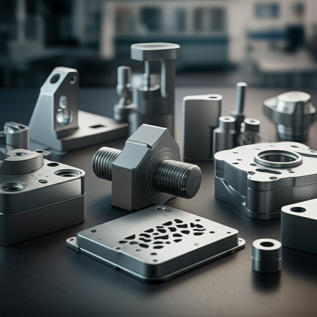
Aluminium rapid prototyping is the process of transforming a CAD design into a functional metal part—quickly and with enough accuracy to simulate the performance of production components. Unlike traditional manufacturing, which might require weeks of tooling and setup, rapid prototyping services use advanced methods like CNC machining, metal 3D printing, casting, and sheet metal fabrication to deliver parts in days. This approach is ideal for applications where you need to test fit, function, or durability before scaling up to full production.
When aluminium outperforms plastics for prototypes
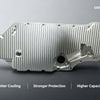
Sounds complex? Imagine you’re developing a bracket that must withstand real mechanical loads or a heat sink for an electronic device. In these cases, plastic prototypes fall short—they can’t match the stiffness, heat tolerance, or fastener performance of aluminium. Choosing aluminium prototyping allows you to:
- Simulate realistic mechanical behavior under load
- Test thermal dissipation in electronics or automotive parts
- Validate fit and function for assemblies that will use metal in production
- Ensure threads and fasteners perform as expected
Typical use cases for aluminium prototypes include:
- Structural housings and brackets
- Heat sinks and thermal management components
- Tooling fixtures and jigs
- Test coupons for material and process validation
Overview of CNC, casting, sheet fabrication, and metal AM
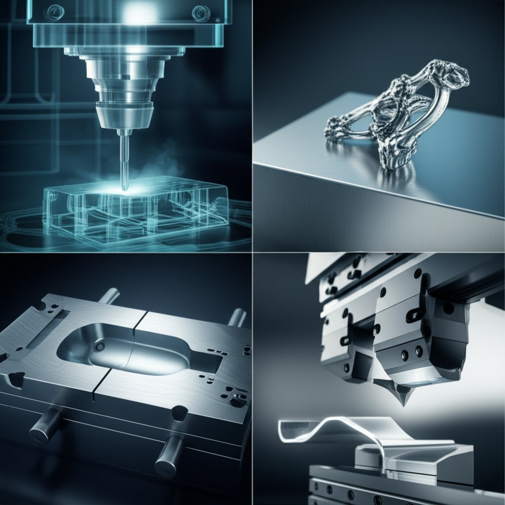
There’s no one-size-fits-all method for aluminium rapid prototyping. Each technique offers unique trade-offs:
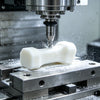
- CNC rapid prototyping: Delivers high precision and excellent surface finish for intricate designs. Best for low to medium volumes and complex geometries.
- Metal prototyping via casting: Useful for creating near-net-shape parts with complex forms, followed by machining for critical features.
- Sheet metal fabrication: Ideal for thin-walled parts, enclosures, and brackets where speed and cost are priorities.
- Metal additive manufacturing (AM): Enables intricate internal features and fast design iterations, though it may have limitations in cost and scalability for some projects.
Choosing the right process depends on your priorities—precision, speed, surface finish, or cost. For example, if you require tight tolerances and a smooth finish, CNC machining is often the go-to. If you need to validate a design for thermal performance, an aluminium prototype can provide results that a plastic model simply cannot.
Benefits of aluminium rapid prototyping
- High strength-to-weight ratio
- Excellent thermal conductivity
- Corrosion resistance for real-world testing
- Faster turnaround compared to traditional metalworking
- Supports realistic mechanical and thermal testing
Limitations to consider
- Potentially higher cost than plastic prototypes
- May require additional post-processing (e.g., deburring, surface finishing)
- Some complex shapes may be challenging or costly to machine
- Longer lead times than basic plastic 3D printing for simple parts
| Property | Aluminium Prototypes | Plastic Prototypes |
|---|---|---|
| Stiffness | High—suitable for load-bearing tests | Low to moderate—limited for structural testing |
| Heat Tolerance | Excellent—good for thermal testing | Poor to moderate—may deform under heat |
| Machining Speed | Moderate—faster than steel, slower than plastics | Fast—quick to machine or print |
| Surface Finish | Fine—can be polished or anodized | Varies—depends on process, usually matte or textured |
So, what is rapid prototyping with aluminium really about? It’s about bridging the gap between concept and production, letting you test, iterate, and validate designs with confidence. If you’re weighing aluminium prototypes against plastics, consider your project’s need for realism in function, thermal performance, and mechanical integrity. In the sections ahead, we’ll guide you through process selection, alloy choice, DFM rules, cost drivers, and how to get fast, accurate quotes—so you can make the smartest choice for your next aluminum prototype.
Choose the Right Prototyping Process for Your Aluminium Prototype
When you’re staring at a new design and wondering how to turn it into a functional aluminium prototype, the sheer number of process options can feel overwhelming. Should you use CNC milling, metal 3D printers, traditional aluminium castings, or lean on sheet metal fabrication? Let’s break down the decision-making into clear, actionable steps—so you can quickly match your requirements to the right prototyping path and avoid costly missteps.
Pick CNC Milling When Tolerances Drive Decisions
Imagine you need a bracket with tight dimensional accuracy or a component with precision holes and threads. CNC milling is your go-to. This process uses computer-controlled cutting tools to shape parts from solid aluminium stock, offering excellent repeatability and surface finish. If your project demands tight tolerances, smooth finishes, and material lot certifications, CNC machining prototyping is a top choice. You’ll notice that for low to medium batch sizes, the flexibility and speed of a CNC mill make it ideal—especially when you need to tweak designs between iterations.
Use Metal AM for Complex Internal Geometry
What if your design includes internal channels, lattice structures, or shapes that traditional machining can’t reach? This is where metal 3d printers and metal 3d printing services shine. Additive manufacturing (AM) builds parts layer by layer, enabling intricate geometries and rapid design changes. For small, complex parts—especially those with features like internal cooling passages—metal AM offers unmatched design freedom. However, be aware that post-processing (such as support removal and surface finishing) is often required to achieve the final part quality.
Choose Castings for Form and Cost at Small Batches
When you need near-net-shape parts with complex forms, aluminium castings like investment casting or die casting are worth considering. These methods are particularly cost-effective for medium to large batch sizes, as the tooling cost is offset by volume. Castings can replicate intricate shapes and deliver good surface finishes, but keep in mind that tolerances are generally looser than with CNC machining, and you’ll need to factor in draft angles and potential porosity. Many teams use castings followed by CNC finishing for critical features.
Leverage Sheet Metal for Thin Features and Speed
Working on enclosures, brackets, or parts with thin profiles? Sheet metal fabrication is fast and efficient for these applications. Prototype sheet metal processes—like laser cutting, bending, and forming—allow for quick turnaround and cost savings on flat or bent parts. While not suitable for every geometry, this route excels when speed and low cost are priorities.
| Process | Lead-Time Drivers | Tolerance Range | Surface Finish | Cost Sensitivity to Volume | Feature Complexity | Common Post-Processes |
|---|---|---|---|---|---|---|
| CNC Milling | Setup, programming, machine queue | Tight (excellent for precision) | Fine (machined, can be polished) | Best for low-medium batches | Moderate-high (depends on tool access) | Deburring, anodizing, surface finishing |
| Metal 3D Printing (AM) | Build prep, print speed, post-processing | Moderate (improves with post-machining) | Coarse to moderate (may need finishing) | Best for small batches, complex parts | Very high (internal features possible) | Support removal, machining, finishing |
| Aluminium Castings | Tooling, mold setup, curing/cooling | Moderate (requires draft, looser than CNC) | Good as-cast, can be improved | Cost-effective at medium-high volume | High (organic/complex shapes) | Machining, deburring, coating |
| Sheet Metal Fabrication | Material availability, setup, forming | Moderate (depends on forming) | Fine to moderate (depends on process) | Excellent for prototypes and low volume | Low to moderate (limited by flat patterns) | Bending, welding, surface finishing |
- Pitfalls to avoid:
- Over-specifying tolerances (drives up cost and lead time)
- Ignoring draft angles for cast parts (can cause defects)
- Neglecting support removal and finishing in metal AM
- Forgetting material certification needs for critical applications
Many successful projects combine these methods—for example, using metal 3d printers for a complex core followed by CNC machining prototyping to finish critical dimensions. The right blend depends on your part’s geometry, required finish, quantity, and budget.
Curious to dive deeper? For a more detailed walk-through of aluminium prototype process choices—including real-world examples—check out our recommended read: What Are the Processes in Aluminum Prototypes?
In the next section, we’ll help you zero in on the best aluminium alloy and surface finish for your prototype goals—ensuring your process choice and material selection work hand in hand.
Select the Right Aluminium Alloy and Finish for Prototyping Success
Ever wondered why one aluminium prototype stands up to harsh environments while another quickly corrodes or fails under stress? The secret is in the alloy and finish you choose. Picking the right combination early in your aluminium rapid prototyping project can mean the difference between a fast win and an expensive do-over. Let’s break down the most popular alloys, how surface finishing (especially anodizing) works, and what to ask suppliers to ensure your prototype aluminum casting or CNC part matches your goals.
Common Prototype Alloys and Why They Matter
Not all aluminium alloys are created equal. Each type brings a unique blend of machinability, strength, corrosion resistance, and finishing characteristics. Here’s a quick rundown of the most common alloys used in cnc aluminium prototyping and aluminum casting projects:
| Alloy | Form | Machinability | Corrosion Behavior | Heat Treatment Response | Anodize Suitability | Typical Use Cases |
|---|---|---|---|---|---|---|
| 6061 | Wrought (Extrusion, Plate, Sheet) | Excellent | High (all tempers) | Good (heat treatable) | Very Good | Structural parts, brackets, consumer electronics, marine gear |
| 7075 | Wrought | Good (can be brittle) | Moderate (poor weldability) | Excellent (high strength) | Good | Aerospace, sports gear, high-stress parts |
| 5052 | Wrought (Sheet) | Very Good | Very High | Non-heat treatable | Good | Enclosures, fuel tanks, wire, rivets |
| A356 (AlSi10Mg) | Casting | Good (after casting) | High | Good (can be heat treated) | Good | Prototype aluminum casting, automotive, complex cast shapes |
For most cnc aluminum prototype jobs, 6061 is a safe, versatile choice—easy to machine, weld, and finish. If you need high strength for critical load-bearing parts, 7075 is worth considering, but keep in mind its lower corrosion resistance and brittleness during machining. For sheet metal work, 5052 aluminum shines with its combination of workability and corrosion resistance. And for aluminum casting projects, A356 (or AlSi10Mg for metal AM) delivers a balance of castability, strength, and finish.
Surface Finishing and Anodizing Readiness
Want your prototype to resist scratches, last longer, or pop with color? Anodizing is a go-to finishing process in aluminium rapid prototyping. Here’s why:
- Corrosion Resistance: Anodized parts form a tough oxide layer, protecting against moisture, chemicals, and wear.
- Durability: Especially with hard anodizing (Type III), you get a thicker, more wear-resistant surface—ideal for high-stress or outdoor parts.
- Aesthetics: Anodizing supports a range of finishes: clear (natural), matte, glossy, or vibrant colors. This makes it perfect for both functional and decorative prototypes.
But not every alloy responds the same way. For example, 6061 and 5052 both anodize well, producing even, attractive finishes. 7075 can also be anodized, but the result may be less uniform—something to consider if appearance is critical. For cast parts, A356 (and similar casting alloys) can be anodized, but surface porosity may affect the final look.
When specifying anodizing for your cnc aluminium prototyping project, consider:
- Type II (Standard): Good for general corrosion resistance and color options
- Type III (Hard): Best for maximum durability and wear resistance
- Clear vs. Color: Clear preserves the natural look; color adds design flexibility
Consistent material and surface prep are key for a quality anodized finish—always confirm with your supplier if your chosen alloy and process are compatible with your finish goals.
How to Ask Suppliers for Material Certs
Imagine you’ve nailed your prototype, but the alloy doesn’t match your spec or fails a critical test. To avoid this, always specify your needs clearly in your RFQ. Here’s a quick checklist for getting it right with aluminum rapid tooling and prototype aluminum casting:
- Specify the exact alloy (e.g., 6061-T6, 5052-H32, A356-T6)
- Indicate temper or heat treatment if required
- Request material certifications per ASTM or Aluminum Association standards
- Ask for traceability (lot numbers, certs) for critical or regulated parts
- Clarify finishing needs (e.g., anodized, color, clear, Type II/III)
- Confirm compatibility of alloy with desired finish and end-use environment
Referencing standards—like ASTM B221 for extruded aluminium or the Aluminum Association’s alloy designations—ensures everyone’s on the same page and reduces the risk of costly mix-ups.
Choosing the right alloy and finish for your cnc aluminum prototype isn’t just about ticking boxes. It’s about matching function, aesthetics, and durability to your real-world needs—so you can move to the next stage with confidence. In the following section, we’ll show you how to apply DFM (Design for Manufacturability) rules that help you avoid rework and keep your prototype project on track.
Apply DFM Rules That Prevent Costly Rework in Aluminium Rapid Prototyping
Ever sent a prototype design for quoting, only to be told it needs major changes—or worse, paid for parts that don’t fit or function? That’s where DFM (Design for Manufacturability) comes in. By applying a few key rules at the design stage, you can save time, reduce costs, and ensure your aluminium rapid prototyping project hits the ground running. Let’s break down actionable DFM tips for each major process, so you can move from CAD to part with confidence.
DFM for CNC Setups and Tool Access
When it comes to precision cnc machining, accessibility and tool selection are everything. Imagine trying to carve a deep, narrow pocket with a tiny cutter—it’s slow, risky, and expensive. Here’s how to avoid common pitfalls:
- Limit pocket depth: Keep pocket depth to less than 3x the diameter of the cutting tool. For example, a 0.5” cutter should not machine pockets deeper than 1.5”. This minimizes tool breakage and chatter.
- Mind wall thickness: For metals, maintain a minimum wall thickness of 0.8 mm. Thinner walls can lead to vibration and poor surface finish.
- Fillet internal corners: Sharp inside corners are difficult and costly to machine. Use internal radii slightly larger than your cutter’s diameter to reduce tool wear and improve surface quality.
- Avoid inaccessible features: Make sure all features can be reached by standard endmills or drills. Features hidden inside pockets or with negative draft angles increase machining time and may not be possible with standard setups.
- Chamfer outside edges: Instead of filleting external edges, which requires special tools, use chamfers for cost-effective finishing.
- Use standard hole types: Prefer cone-bottomed holes (created by standard twist drills) over flat-bottomed holes, which require additional operations.
By following these prototype cnc machining guidelines, you’ll notice faster quoting, fewer change requests, and smoother production runs—hallmarks of effective rapid prototyping cnc machining.
DFM for Casting Draft and Gating
Designing for aluminium casting isn’t just about shape—it’s about making sure the part can be removed from the mold and finished efficiently. Here’s what to watch for:
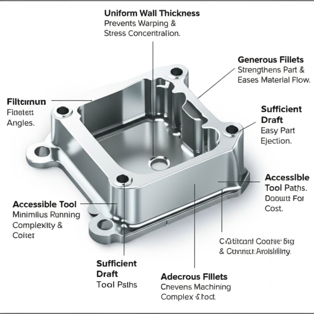
- Maintain uniform wall thickness: Avoid walls that are too thin (risking weakness) or too thick (causing shrinkage and waste). Find a balance for strength and cooling efficiency.
- Apply draft angles: Use at least 1–3 degrees of draft on all vertical faces. This helps parts release from the mold cleanly and reduces rework.
- Round transitions: Replace sharp corners with fillets to reduce stress concentrations and cracking. Radii also improve metal flow in the mold.
- Plan for gating and risers: Work with your foundry to design gating systems that minimize voids and ensure even metal distribution.
- Account for shrinkage: Design with expected cooling shrinkage in mind to avoid warping or dimensional errors.
- Leave machining stock: For critical surfaces, add extra material for post-casting cnc fabrication or finishing.
Following these DFM pointers ensures your casting is robust and ready for machining, reducing the risk of defects and costly iterations.
DFM for Metal AM Supports and Overhangs
Metal additive manufacturing (AM) offers incredible design freedom, but it comes with its own set of DFM rules. To keep post-processing and costs down:
- Design self-supporting angles: Avoid overhangs greater than 45°, which require support structures and extra finishing.
- Use lattice structures judiciously: Lattices can save weight and material but may complicate powder removal and inspection.
- Plan for support removal: Place supports in non-critical areas and ensure they can be accessed for removal after printing.
- Allow for datum pads: Add flat surfaces for cnc prototype machining or inspection after printing.
- Consider powder removal paths: Ensure all internal cavities can be cleaned out post-build.
These steps keep your metal AM parts functional and manufacturable, and set you up for efficient downstream cnc machining rapid prototyping.
DFM for Sheet Features and Bend Radii
Sheet metal rapid prototyping is all about speed and simplicity, but ignoring a few basic rules can lead to warped, distorted, or unworkable parts. Here are essential DFM tips for sheet metal fabrication:
- Align bend radii with material thickness: Use a bend radius equal to or greater than the material thickness for best results.
- Keep flange lengths at least 4x material thickness: Shorter flanges may not form correctly.
- Maintain hole-to-edge distances: Holes should be at least the material thickness from the edge (or 0.062” for thin material, 0.125” for thicker stock).
- Use consistent radii across bends: This simplifies tooling and accelerates production.
- Design reliefs at corners: Prevent tearing and distortion during bending.
- Follow standard countersink sizes and angles: Use standard diameters and angles to avoid special tooling.
These DFM rules make metal laser cutting and sheet forming faster, less prone to error, and more affordable for prototype runs.
DFM Checklist by Process
| Process | Key DFM Rules |
|---|---|
| CNC Machining |
|
| Aluminium Casting |
|
| Metal AM |
|
| Sheet Metal |
|
Before you freeze your design or send out for quotes, run through these DFM checklists. And if you’re unsure, ask your supplier for feedback—they’ll often spot challenges early, especially for cnc fabrication or prototype cnc machining jobs.
Ready to move forward? Next, we’ll show you how to estimate costs and lead times for each process, so you can plan your aluminium rapid prototyping project for maximum efficiency.
Understand Cost and Lead Time Like a Pro in Aluminium Rapid Prototyping
Ever looked at a quote for aluminium rapid prototyping and wondered, “Why does this prototype part cost so much more than a production piece?” Or maybe you’re racing against a deadline and need to know how to speed up delivery without blowing your budget. Let’s break down the real drivers behind machinist metal cost, what impacts lead times, and how you can optimize both for your next batch of prototype parts.
What Really Drives Per-Part Cost?
When you request a quote for manufacturing prototypes, you’ll notice that several factors combine to set the final price. The biggest drivers are:
- Material Costs: The aluminium alloy you choose can range widely in price. Softer grades like 6061 are more affordable and easier to machine, while high-strength grades like 7075 cost more and require slower, more careful machining. For CNC rapid prototyping, raw aluminium billets might be a fraction of the total, but for casting, the cost of specialty alloys and waste can add up fast.
- Setup and Programming: Setting up a CNC machine for a new job—programming, fixturing, and tool changes—represents a major chunk of the cost for one-off or low-volume prototype machining. This is why a single prototype can cost three to five times more per part than a production run, where setup costs are spread over many units.
- Machine Time: The complexity of your part—tight tolerances, deep pockets, thin walls—directly impacts how long it takes to machine. More intricate designs require slower feeds, specialty tools, and more passes, all of which drive up both machinist metal cost and lead time.
- Post-Processing: Surface finishing, deburring, anodizing, or secondary machining can increase costs by 15–40%, especially for premium finishes or tight cosmetic specs.
- Tooling and Pattern Costs (for Casting): Aluminium casting cost includes the expense of making molds or patterns. For small batches, this upfront investment can be significant, but it pays off as batch size increases.
| Process | Key Cost Drivers | Lead-Time Drivers | Optimization Tips |
|---|---|---|---|
| CNC Machining | Setup, machine time, material waste, complexity | Machine queue, programming, inspection | Standardize features, relax non-critical tolerances, combine setups |
| Aluminium Casting | Tooling, alloy selection, post-machining | Mold build, curing/cooling, batch scheduling | Use standard alloys, minimize mold changes, optimize gating |
| Sheet Metal Manufacturing | Material utilization, setup, forming operations | Material availability, setup, forming/bending | Nest parts, use standard gauges, align bends to minimize setups |
| Metal Additive Manufacturing | Build prep, machine time, post-processing | Queue time, build speed, support removal | Minimize supports, optimize orientation, batch similar parts |
How Batch Size Changes Unit Economics
Ever wondered why a single prototype part can be so expensive, but the price drops dramatically for a batch of ten or more? It’s all about spreading setup and programming costs across more units. For small runs (under 10 units), setup can be 40–60% of total cost. For batches over 100, that drops to 5–15%. Larger batches also unlock material discounts and more efficient sheet metal manufacturing or rapid sheet metal processes.
- For prototype machining, consider grouping similar parts or consolidating orders to reduce per-part cost.
- In aluminum casting cost, higher volumes justify the tooling investment—making casting more attractive for medium to large runs.
- For fast prototyping with sheet metal, nesting multiple parts in a single sheet saves both material and setup time.
Lead-Time Levers You Control
Lead time isn’t just about how fast a shop can run a machine. It’s a combination of:
- Machine Queue: How many jobs are ahead of yours?
- Tooling Availability: Are custom fixtures or molds required?
- Inspection Scope: Critical features or tight tolerances add time for quality checks.
- Post-Finish Capacity: Surface treatments like anodizing can introduce bottlenecks.
Want to speed things up? Relax non-critical tolerances, choose standard finishes, and clarify which features are truly essential for your prototype parts. Communicate early about inspection and certification needs—this helps your supplier plan and may reduce delays.
Sustainability and Scrap: The Hidden Cost Factor
Aluminium is highly recyclable, making it a smart choice for sustainable manufacturing prototypes. However, the process you choose affects both energy use and scrap rates. CNC machining is efficient for simple shapes but can waste material for highly contoured parts. Sheet metal manufacturing and rapid sheet metal processes maximize material use through nesting. Casting can recycle sprues and runners, but may have higher energy intensity per part for small batches.
If suppliers provide setup vs. run-time breakouts, you can compare economies of scale; focus on relative differences rather than just the final quote. This transparency helps you make informed trade-offs between speed, cost, and function.
Understanding these drivers lets you ask the right questions and compare apples-to-apples when sourcing your next aluminium rapid prototyping job. In the next section, we’ll cover how to plan inspection and validation—so you can be sure your prototype parts meet every expectation before moving to production.
Plan Inspection and Validation for Success in Aluminium Rapid Prototyping
Imagine investing in an aluminium prototype that looks perfect—until you discover a critical dimension is off, or the material isn’t what you specified. Sounds stressful? That’s why a smart inspection and validation plan is essential for every aluminium rapid prototyping project. Let’s break down how to verify dimensions, materials, and function without bogging down your schedule or budget. By the end, you’ll know how prototype manufacturers and engineering teams keep quality on track, and how you can, too.
Dimensional Inspection That Matches Tolerances
When do you need a simple caliper check, and when is it worth investing in advanced measurement tools? The answer depends on your part’s complexity and the tolerances that matter most. For straightforward features—like outer diameters or hole sizes—manual tools such as calipers, micrometers, and height gauges are fast and cost-effective. But for complex geometries, tight tolerances, or intricate surfaces, Coordinate Measuring Machines (CMMs) or optical scanners deliver precise, repeatable results.
| Inspection Method | Purpose | Best For | Typical Documentation |
|---|---|---|---|
| Calipers & Micrometers | Quick checks of basic dimensions | Simple features, low-risk parts | Manual logs, basic inspection sheets |
| Height Gauges | Measuring step heights, flatness | Flanges, bosses, parallel faces | Inspection reports, operator notes |
| CMM (Coordinate Measuring Machine) | High-precision, 3D measurement | Complex surfaces, tight tolerances | Digital inspection reports, 3D data |
| Optical/3D Scanning | Rapid comparison to CAD models | Freeform shapes, surface profiles | Color maps, deviation analysis |
Prototype machining services often tailor their inspection approach to the part’s critical features and project stage. Early builds might focus on must-hit datums and interfaces, while production-intent prototypes may require full CMM validation. Align your inspection effort with risk: over-inspecting non-critical features wastes time, but skipping checks on vital interfaces can derail your project.
Material Verification and Certifications
Ever worried your prototype fabrication supplier might substitute a lower-grade alloy? Material mix-ups are rare but can be costly, especially for safety-critical or regulated projects. That’s why prototype manufacturers and sourcing managers insist on clear, documented material verification.
- Mill Certificates (MTCs): Request a material test certificate for each batch, showing chemical composition and mechanical properties per ASTM or Aluminum Association standards. This is your first line of defense for material traceability and compliance.
- Third-Party Inspection: For high-stakes projects, consider independent lab verification (e.g., SGS, BV, TUV) to confirm alloy and properties.
- Non-Destructive Testing (NDT): For castings or structural parts, NDT methods—like dye-penetrant or X-ray—can detect hidden porosity or cracks without damaging the part.
- Hardness Testing: When heat treatment or hardness is critical, ask for Rockwell or Brinell test results as part of your inspection documentation.
These steps are standard for engineering prototype services and prototype development services, especially in aerospace, automotive, or medical applications. They help ensure you get exactly the material you specified, every time.
Functional Tests and Acceptance Criteria
How do you know your prototype isn’t just dimensionally and materially correct, but truly fit for purpose? That’s where functional testing and clear acceptance criteria come in. Prototype and short run services often work with customers to define what “success” looks like for each stage of development.
- Critical dimensions and interfaces must meet tolerance (e.g., mating faces, hole locations)
- Material certifications match specified alloy, temper, and traceability requirements
- Functional features operate as intended (e.g., moving parts, load-bearing areas)
- Cosmetic standards for visible surfaces (if required)
- No critical defects (e.g., cracks, porosity, inclusions) as confirmed by NDT or visual inspection
For example, you might specify that a bracket must support a defined load without deformation, or that a heat sink must dissipate a set amount of thermal energy. Usability and regulatory testing—especially for medical or electronic products—should be built into your prototype validation plan from the start.
Sample Acceptance Criteria Outline
- All must-hit datums and interfaces within specified tolerance
- Material certs provided for each lot; matches alloy and temper
- Functional tests (as defined) passed
- Visual inspection: no cracks, major porosity, or surface defects
- Documentation: inspection report, material certs, NDT (if required)
Aligning your inspection and validation plan with the risk and stage of your project reduces rework and keeps your aluminium rapid prototyping on track. When you work with experienced prototype manufacturers, you benefit from proven protocols and trusted documentation—helping you move confidently toward production.
Next, we’ll show you how to build a bulletproof RFQ and quoting checklist, so you get fast, accurate quotes and avoid surprises as you scale from prototype to production.
Use This RFQ Template and Quoting Checklist for Aluminium Rapid Prototyping
When you’re ready to turn your 3D model into a real aluminium part, getting a fast, accurate quote is crucial. But have you ever sent out an RFQ (Request for Quotation) only to get vague, mismatched responses from suppliers? Or worse, received quotes that don’t cover your actual needs? It’s a common pain point—especially for those new to prototyping services or juggling multiple vendors. Let’s simplify the process with a practical RFQ template, a step-by-step checklist, and tips for comparing quotes with confidence.
What Files and Callouts Suppliers Need
Imagine you’re a supplier receiving a quote request. What would help you deliver an accurate, apples-to-apples quote? The answer: complete, clear documentation. Here’s what to include every time you reach out to a cnc prototyping service or product prototyping services provider:
- 3D CAD File (Native + Neutral): Send your native CAD file (e.g., SolidWorks, Inventor) and a neutral format like STEP (.stp) or IGES (.igs). This ensures compatibility with any online cnc service or in-house quoting platform.
- 2D PDF Drawing: Include a drawing with all critical dimensions, tolerances, thread specs, and special notes. Highlight features that are fit-critical or require specific finishes.
- BOM (Bill of Materials): If your project is an assembly, attach a simple BOM listing each part, material, and quantity.
- Surface Finish and Color Requirements: Clearly state if you need anodizing, powder coating, or a specific polish level.
- Inspection and Certification Needs: Note if you require CMM reports, First Article Inspection (FAI), or material certs.
- Target Lead-Time: Specify your ideal delivery date—many cnc machining online platforms offer expedited options.
Providing these details up front helps companies that build prototypes deliver quotes that truly match your project scope.
How to Specify Alloys, Finishes, and Inspection
Not all aluminium is created equal, and a missed detail here can lead to costly rework. Be as specific as possible when describing your requirements for rapid prototype tooling or prototype design services:
- Alloy & Temper: Clearly state the aluminium grade (e.g., 6061-T6, 7075-T6, A356) and temper if relevant.
- Finish: Indicate if you want parts anodized (Type II clear, Type III hard, or colored), powder coated, or simply deburred.
- Tolerances: Highlight only those dimensions that are truly critical. For general features, use standard tolerances (e.g., ±0.1 mm) unless a tighter spec is essential.
- Inspection Scope: Specify if you need basic dimensional checks, full CMM reports, or functional testing. The more you clarify, the less chance for miscommunication.
- Certification: Request material certs and compliance with standards (ASTM, Aluminum Association) where required.
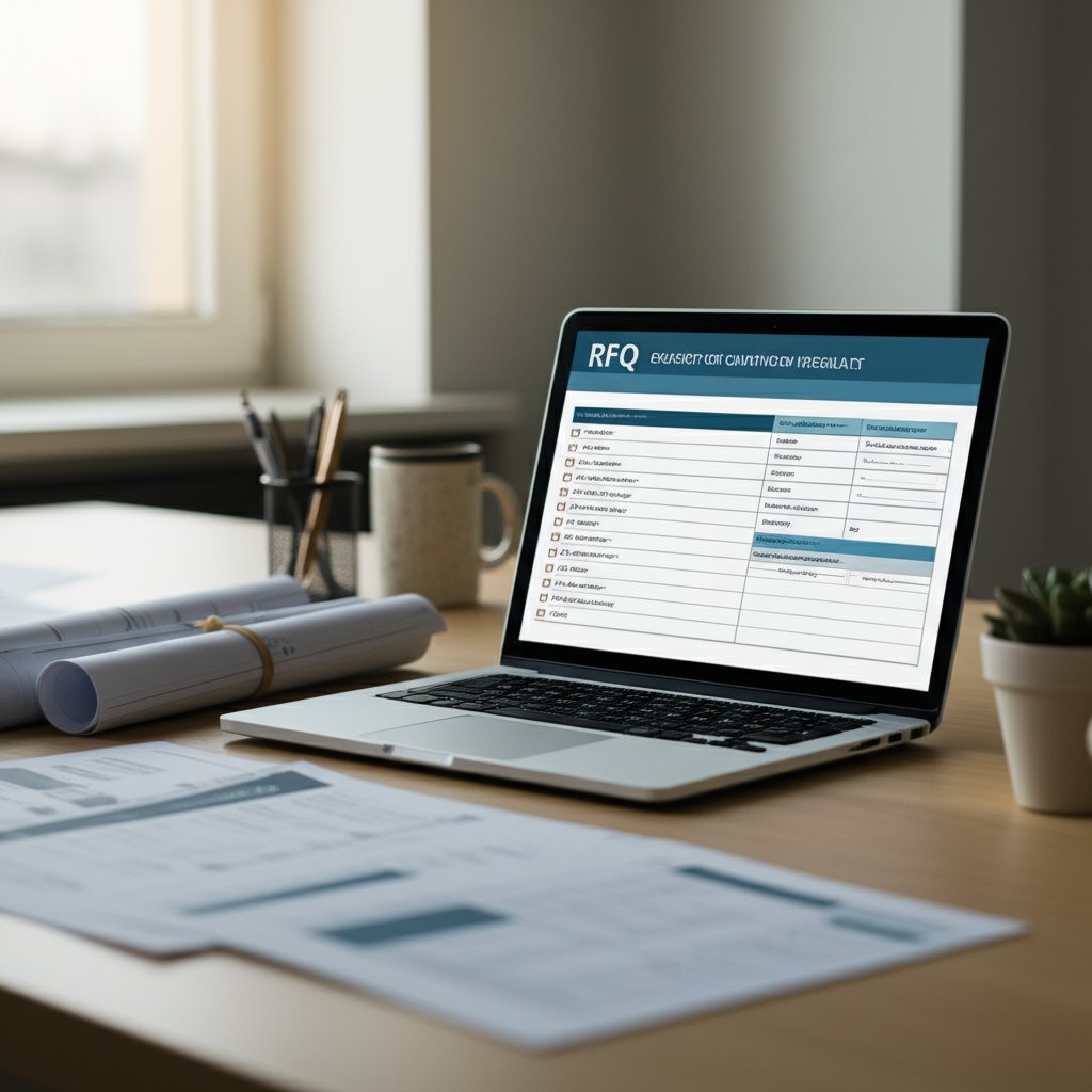
Copy-and-Paste RFQ Template
Request for Quotation (RFQ) Template – Aluminium Rapid Prototyping
- Company Name: [Your Company]
- Contact Person: [Your Name]
- Email/Phone: [Your Contact Info]
- Part Name/Description: [E.g., Gearbox Housing, Bracket]
- Quantity: [Number of Units]
- Material/Alloy & Temper: [E.g., 6061-T6, 7075-T6]
- Finish Requirements: [E.g., Anodized (Type II, Clear), Powder Coated]
- Critical Dimensions/Tolerances: [List or refer to attached 2D drawing]
- Inspection Scope: [E.g., Basic QC, CMM, FAI]
- Certification Needs: [E.g., Material Certs, RoHS, REACH]
- Target Lead-Time: [Delivery Date or Range]
- Delivery Address: [Your Address]
- Attachments: [CAD, PDF, BOM]
Copy, paste, and fill in your details—then send to your shortlist of prototyping services or cnc prototyping service vendors. This format keeps your requests clear and comparable.
Quoting Checklist: Get the Details Right
| Checklist Item | Purpose |
|---|---|
| 3D CAD File (STEP/IGES) | Accurate geometry import for quoting |
| 2D Drawing with Tolerances | Highlights critical features and specs |
| BOM (if assembly) | Clarifies part count and materials |
| Surface Finish Requirement | Ensures correct post-processing |
| Inspection/Certification Needs | Defines QA expectations |
| Target Lead-Time | Sets delivery expectations |
| Delivery Address | For shipping quote accuracy |
Questions to Ask Vendors Before You Commit
- Can you confirm process capability for my tolerances and alloy?
- Are material certs and inspection reports included?
- Is the quote all-inclusive (material, machining, finishing, inspection, shipping)?
- What is your typical lead time for similar prototype parts?
- How are changes or revisions handled after quoting?
- Is this a fixed or estimated price?
How to Compare Quotes Fairly
When the quotes start arriving, it’s tempting to just sort by price. But for a true comparison, make sure you’re evaluating:
- Same material grade and temper
- Identical surface finish and inspection scope
- Consistent tolerances and feature specs
- Lead time and shipping terms
- Breakdown of setup vs. per-unit price (if available)
Requesting this level of detail helps you avoid surprises—and makes it easy to spot the best value among companies that build prototypes, whether you’re using an online cnc service or a boutique shop.
With this RFQ template and quoting checklist, you’ll cut down on back-and-forth, improve quote accuracy, and set your aluminium rapid prototyping project up for success. Next, we’ll explore what to look for in a prototyping partner, so you can move from quote to production with confidence.
Choose the Right Prototyping Partner for Aluminium Rapid Prototyping Success
Ever wondered why some aluminium rapid prototyping projects run smoothly, while others hit roadblocks with delays or quality issues? The answer often comes down to your choice of partner. Whether you’re a startup racing to validate a design or an established manufacturer scaling up, picking the right rapid prototyping company can mean the difference between a fast win and costly setbacks. Let’s break down what to look for in a partner, how to compare top rapid prototyping companies, and when it makes sense to consolidate everything under one roof.
How to Evaluate Rapid Prototyping Partners
Sounds complex? Imagine you’re reviewing a shortlist of vendors. What should you check first? Start by looking at technical capabilities—do they offer the full range of aluminium prototyping solutions you need, such as CNC machining, casting, sheet metal fabrication, and metal additive manufacturing? A broad process portfolio means you won’t have to juggle multiple prototype manufacturers for a single project.
- Technical Breadth: Can the partner deliver both simple and complex aluminium prototypes, from rapid CNC to intricate castings?
- Material Coverage: Do they stock or source the aluminium alloys you need—like 6061, 7075, or A356?
- Industry Experience: Have they produced parts for your sector (e.g., aerospace, automotive, electronics)?
- Lead-Time Flexibility: Are fast-turn, last-minute changes possible?
- Communication: Is there a dedicated project manager or direct technical support?
Don’t forget to check reviews and case studies—these offer real-world proof of reliability, responsiveness, and quality. It’s not just about price; it’s about finding a rapid prototyping company that aligns with your speed, quality, and flexibility needs.
Comparing Capabilities and Quality Systems
When you compare prototype companies side by side, you’ll notice that some stand out for their breadth of services, while others excel in niche areas. Here’s a comparative snapshot to help you weigh your options. Notice how ISO certifications, DFM (Design for Manufacturability) support, and transparency in pricing can set a partner apart for demanding aluminium rapid prototyping jobs:
| Provider | Key Processes | Aluminium Alloy Coverage | Lead-Time Options | DFM Support | Quality Certifications | Pricing Transparency |
|---|---|---|---|---|---|---|
| XTJ Rapid Prototyping Services | CNC Machining, Die Casting, Injection Molding | 50+ materials (6061, 7075, A356, more) | Rapid (expedited available) | Complimentary DFM feedback | ISO 9001:2015 | Clear, detailed quotes |
| Protolabs | CNC, 3D Printing, Sheet Metal | Standard grades (6061, 7075) | 1–7 days | Automated DFM in quoting | ISO 9001:2015 | Online instant quoting |
| RapidDirect | CNC, Injection Molding, 3D Printing, Sheet Metal | Wide range, incl. aluminium alloys | 1–5 days | DFM review on request | ISO 9001:2015 | Transparent, itemized |
| HY Proto | 3D Printing, CNC, Injection Molding | Multiple metals/plastics | 1–3 days (3D print), longer for CNC | DFM guidance via support | ISO 9001:2015 | Online quoting |
| Going Rapid | 5-axis CNC Aluminium Prototyping | Aluminium specialist | 72-hour turnaround | Design optimization, audit | Trusted QC | Custom quotes |
You’ll see that leading rapid prototyping companies offer much more than just machining—they combine process variety, short lead times, and robust quality systems to deliver reliable prototyping solutions. For example, XTJ’s Rapid Prototyping Services stand out for their wide material selection, free DFM support, and ISO 9001:2015 certification, making them a strong choice for demanding aluminium projects where quality and speed are non-negotiable.
When to Consolidate Processes Under One Roof
Is it worth working with a single provider for everything, or should you split work among several prototype manufacturers? Here’s how to decide:
-
Consolidate when:
- Your project requires multiple processes (e.g., casting plus CNC finishing, or sheet metal and 3D printing)
- You value a single point of contact for project management and accountability
- Speed, DFM feedback, and quality consistency are top priorities
-
Split vendors when:
- You need ultra-specialized capabilities (e.g., niche finishing, exotic alloys)
- Cost is the sole driver and you’re willing to manage coordination
Many rapid prototyping companies now offer integrated solutions—so you can move from design to finished part without delays, miscommunication, or quality gaps. This approach is especially valuable for metal prototyping services where DFM feedback, traceability, and post-processing all need to work in sync.
Key Takeaways for Selecting a Prototyping Partner
- Prioritize partners with a proven track record, broad technical capabilities, and transparent communication
- Look for ISO 9001:2015 or equivalent certifications for quality assurance
- Choose vendors offering DFM support and clear, detailed quotes
- Consider consolidating under one roof for complex, multi-process projects
- Always align your choice with project goals—speed, quality, flexibility, and budget
By following these guidelines, you’ll be equipped to select a partner who can deliver rapid prototype services tailored to your needs—helping you bring your aluminium rapid prototyping project to life quickly and confidently. In the next section, we’ll tie everything together with an actionable step-by-step plan for moving from design to finished prototype, ensuring you know exactly where to get a prototype made and how to scale up as your project evolves.
Turn Insights into an Actionable Aluminium Rapid Prototyping Plan
Ready to move from theory to practice? If you’ve ever wondered how to turn all the details—processes, alloys, DFM, cost, and QA—into a repeatable workflow, you’re not alone. Many teams get stuck at the transition from design to quote, or struggle to scale from a rapid prototype to a production-ready part. Let’s break it down into a clear, seven-step plan that answers not just how to get started, but also where to get a prototype made and how to keep your project on track from first sketch to pilot run.
Your Seven-Step Aluminium Prototype Plan
-
Clarify Your Requirements
Define the prototype’s purpose—mechanical, thermal, fit, or cosmetic testing? List must-have specs, key tolerances, and any regulatory or customer requirements. This clarity will steer every downstream decision. -
Consult the Process Selection Matrix
Match your needs to the right process: CNC machining for tight tolerances, metal rapid prototyping (3D printing) for complex internals, casting for batch efficiency, or sheet metal for speed. Use the earlier comparison table to weigh trade-offs between cost, speed, and finish. -
Select the Best Alloy and Finish
Choose an aluminium alloy that fits your prototype’s demands—6061 for versatility, 7075 for strength, 5052 for forming, or A356 for castings. Confirm the finish (anodizing, powder coat, etc.) with your supplier to ensure compatibility and durability. -
Apply DFM Checklists Early
Before you freeze your CAD, run through DFM rules for your chosen process. Are wall thicknesses, draft angles, and fillets within recommended ranges? This step minimizes costly redesigns and accelerates quoting. -
Scope Inspection and QA Requirements
Decide which features are critical and what level of inspection is needed—manual checks, CMM, material certs, or NDT. Specify these in your documentation so nothing gets missed later. -
Issue a Complete RFQ to Shortlisted Partners
Send your files, drawings, and specs to trusted prototype services. If you’re still deciding where to get a prototype made, consider partners offering CNC, casting, and DFM feedback under one roof. For example, Rapid Prototyping Services from XTJ provide complimentary DFM review, ISO 9001:2015 quality, and a broad range of aluminium alloys—making them a strong option for projects needing reliability and speed. -
Review Quotes Using the Cost Drivers Table
Compare not just price, but process, lead time, inspection scope, and included finishes. Use the earlier cost drivers table to spot hidden setup fees or post-processing costs. Ask for clarifications before you commit, so your rapid prototyping manufacturing stays on schedule and budget.
Lock in DFM and QA Before You Quote
Imagine discovering a design issue or missing certification requirement only after parts are made. Painful, right? Locking down DFM and QA before you quote is the best way to avoid this. Share your DFM checklist and QA plan with suppliers upfront. This transparency helps prototype development companies spot challenges early, offer suggestions, and deliver faster, more accurate results.
Scale from Prototype to Pilot with Confidence
Once your first rapid prototype is validated, scaling up becomes a matter of refining—not reinventing—the process. Use lessons learned from inspection and functional tests to tweak your design or process. If you chose a partner with broad capabilities, you can often move from prototype to pilot or low-volume production without switching vendors, saving time and ensuring consistent quality.
Key Takeaways:
"A structured, step-by-step workflow—covering requirements, process, material, DFM, QA, quoting, and review—lets you move from CAD to finished aluminium prototypes with speed and confidence. Don’t leave sourcing to chance: clarify specs, ask the right questions, and choose partners who offer both technical breadth and quality assurance. That’s how you win in metal rapid prototyping."
Sustainability Actions for Smarter Prototyping
- Design for recyclability—select alloys and finishes that support easy recycling
- Minimize machining waste—use near-net-shape processes when possible
- Specify recycled content—where supported by your supplier, request recycled aluminium
By following this plan, you’ll not only know where to get a prototype made, but also how to make every step—from design to delivery—efficient, reliable, and ready for scale-up. With the right partner, clear documentation, and a focus on both performance and sustainability, your aluminium rapid prototyping projects will deliver fast wins and long-term value.
Frequently Asked Questions about Aluminium Rapid Prototyping
1. What are the main methods used in aluminium rapid prototyping?
The primary methods for aluminium rapid prototyping include CNC machining, metal 3D printing (additive manufacturing), casting, and sheet metal fabrication. Each method offers unique benefits—CNC provides high precision and finish, metal AM enables complex geometries, casting is efficient for batch production, and sheet metal is ideal for thin, fast prototypes. The choice depends on your part’s geometry, tolerance, batch size, and end-use requirements.
2. When should I choose aluminium over plastic for prototypes?
Choose aluminium when your prototype must withstand real mechanical loads, require heat dissipation, or demand realistic mechanical testing. Aluminium prototypes are ideal for functional testing, structural parts, and thermal applications where plastics would not accurately simulate end-use conditions.
3. What are the common alloys used for aluminium prototypes?
Popular alloys for aluminium prototypes include 6061 (versatile and easy to machine), 7075 (high strength), 5052 (great for sheet metal), and A356 (common for castings). Alloy selection depends on your prototype’s needs for strength, corrosion resistance, machinability, and finishing options like anodizing.
4. How do I ensure quality and accuracy in my aluminium prototypes?
Quality assurance involves matching inspection methods to part complexity and tolerance needs. Use calipers or micrometers for basic checks, and CMMs or optical scanners for intricate features. Always request material certifications, specify critical dimensions, and outline functional tests in your RFQ to align with suppliers’ quality processes.
5. What factors affect the cost and lead time of aluminium rapid prototyping?
Key cost drivers include material selection, setup and programming time, part complexity, and post-processing needs. Lead time is influenced by machine availability, tooling, inspection requirements, and finishing steps. Batch size also impacts both cost and delivery—larger runs can lower per-part pricing by distributing setup costs.