
CNC Aluminium Prototyping: 9 Essential Points From CAD To QA
CNC Aluminium Prototyping
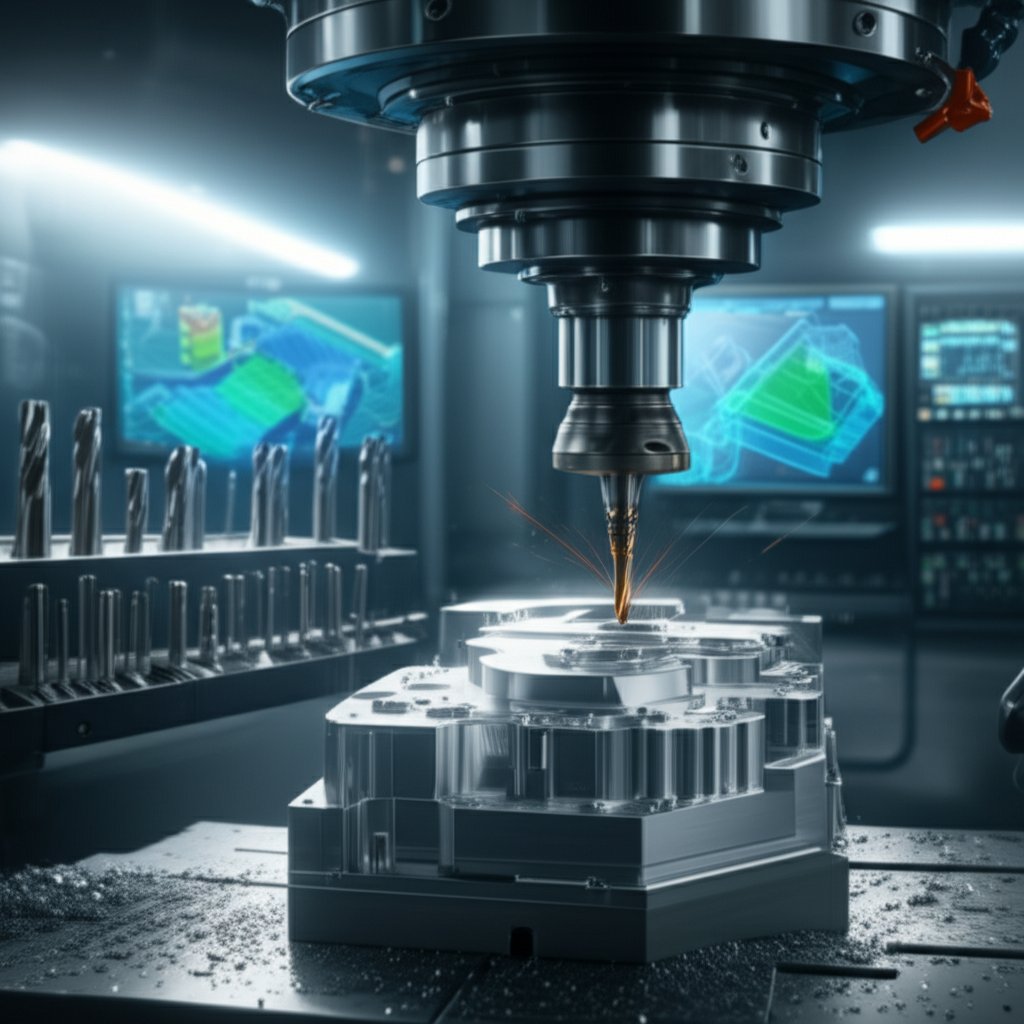
Ever wondered how engineers turn a digital idea into a real, testable aluminum part—often in just days? That’s the power of cnc aluminium prototyping. Whether you’re designing a heat sink for electronics or a precision fixture for automotive testing, this method bridges the gap between concept and function with speed and precision.
What CNC Aluminium Prototyping Means
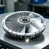
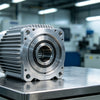
At its core, CNC aluminium prototyping uses Computer Numerical Control (CNC) machines—like mills and lathes—to carve, cut, and shape solid blocks of aluminum into detailed, functional prototypes. Unlike manual machining, CNC relies on digital instructions from CAD models, ensuring repeatable accuracy and enabling complex shapes that would be difficult to produce by hand. This process is a subset of cnc machining prototyping, and is especially valued for its ability to deliver both visual and fully functional prototypes.
When CNC Beats 3D Printing or Casting
Sounds complex? Actually, CNC aluminium prototyping often stands out when you need:
- Dimensional accuracy—tight tolerances for moving parts or precision fits
- Material properties—real aluminum alloys for strength, conductivity, and durability
- Surface finish—smooth, clean surfaces ready for anodizing, coating, or assembly
- Iterative speed—quick turnaround for design tweaks without waiting for molds
- Compatibility—a wide range of alloys for different performance needs
Compared to 3D printing, which excels at rapid, complex shapes but may lack strength or finish, CNC machining delivers real-world mechanical performance and a professional look. Unlike casting, which requires expensive tooling and is better for mass production, CNC milling machining is cost-effective for one-offs and small batches.
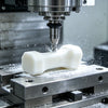
From Concept to Functional Parts Without Tooling
Imagine you need a prototype bracket that must withstand real loads, or a heat sink to test thermal performance. With CNC aluminium prototyping, you can go from a CAD file to a finished part—no custom molds or dies required. The typical workflow involves:
- CAD design of the part
- CAM programming to generate toolpaths (what is cnc milling?—it’s the process of removing material using rotating cutters)
- Material selection and preparation
- CNC milling turning or CNC turning, depending on the geometry
- Finishing steps like deburring or surface treatment
- Inspection for accuracy and quality
This rapid sequence is why industries like aerospace, automotive, and electronics rely on CNC prototyping for housings, test coupons, fixtures, and more.
Typical Tolerances and Surface Expectations
One of the main reasons engineers choose CNC aluminium prototyping is the ability to achieve tight tolerances and consistent surface finishes. While exact numbers depend on the machine and setup, you’ll notice that CNC parts generally outperform 3D prints in accuracy and feel. Finishing options—such as anodizing, bead blasting, or polishing—can further enhance both appearance and performance.
-
Benefits:
- Excellent repeatability and precision
- Functional prototypes with real material properties
- Wide range of alloys and finishes
- Fast iteration from digital design to part
-
Pitfalls:
- Material waste due to subtractive process
- Higher cost per part for complex shapes vs. 3D printing
- Design limitations based on tool access and geometry
Key Takeaway: Choose CNC aluminium prototyping when your project demands real-world strength, tight tolerances, and a professional finish—especially for functional testing or when moving toward production.
Curious about the step-by-step process or want to dive deeper into aluminum prototyping? Check out this detailed guide on aluminum prototype processes for more insights.
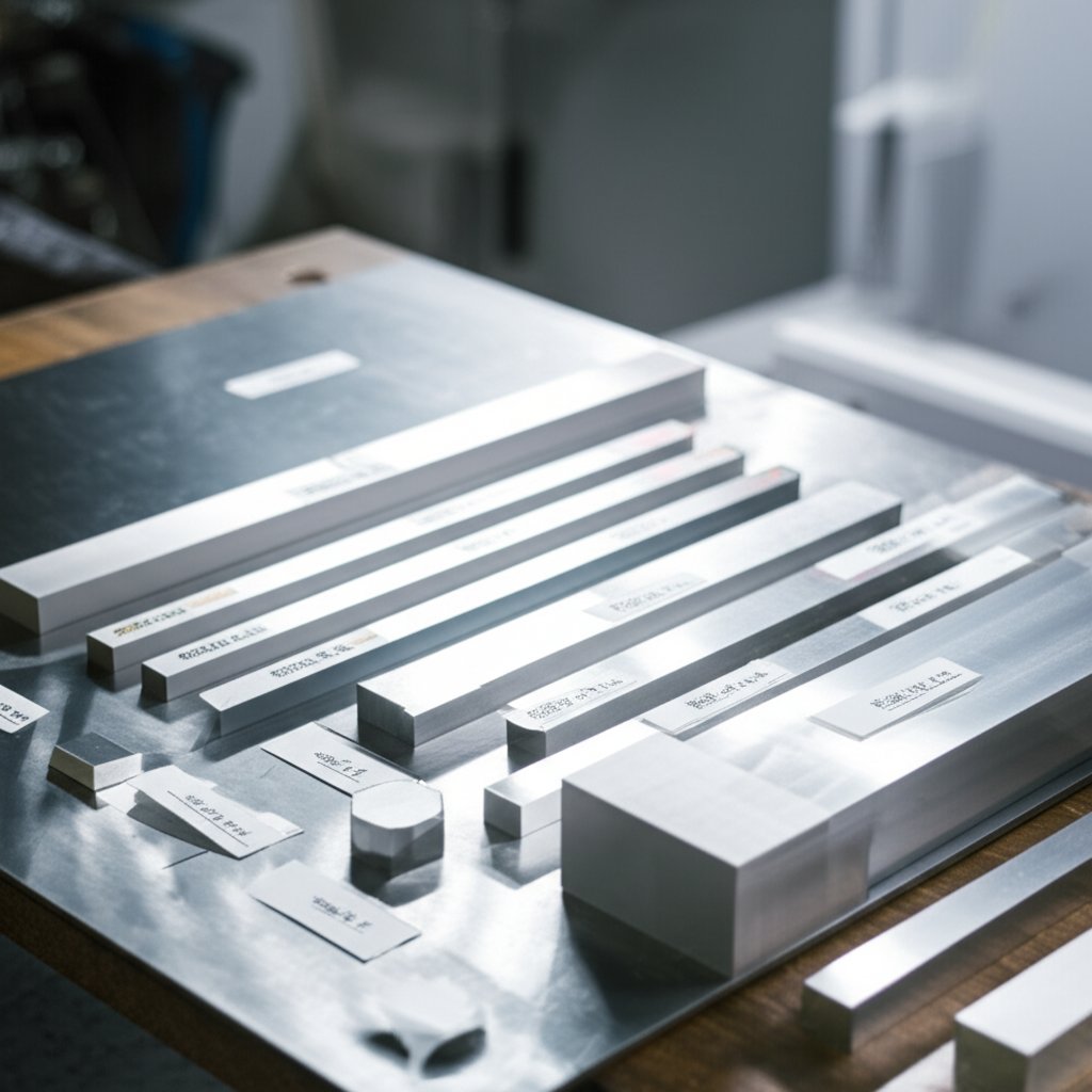
Alloy Selection for CNC Aluminium Prototyping
Choosing the right aluminum alloy can make or break your CNC aluminium prototyping project. Imagine spending hours on a complex part, only to find it warps in a humid environment or is too brittle for testing. How do you avoid these pitfalls? It starts with understanding the strengths, weaknesses, and best-fit scenarios for each alloy. Let’s break down the options and help you make a confident, informed choice for your next prototype.
How to Pick the Right Alloy for Your Prototype
Not all aluminum alloys behave the same under a cutting tool or in the field. Some are easy to machine and finish, while others offer superior strength or corrosion resistance. Your selection should align with your prototype’s end use—whether that’s structural load, cosmetic finish, or environmental durability. Here’s a decision matrix that compares the most common alloys for aluminium cnc machining:
| Alloy | Machinability | Relative Strength | Corrosion Resistance | Weldability | Heat Treatability | Anodizing Quality | Typical Prototype Use Cases | Common Tempers |
|---|---|---|---|---|---|---|---|---|
| 6061-T6 | Excellent | Medium-High | Good | Very Good | Yes (T6) | Very Good | Brackets, enclosures, fixtures, frames | T6, T4 |
| 7075-T6 | Good | Very High | Moderate | Poor | Yes (T6) | Good | Load-bearing, aerospace, sporting goods | T6, T651 |
| 5052-H32 | Good | Medium | Excellent | Very Good | No | Fair | Marine, tanks, panels, pressure vessels | H32 |
| 2024-T3 | Fair | High | Poor | Poor | Yes (T3) | Fair | Aerospace, high-stress parts, military | T3 |
| 5083 | Fair | Medium-High | Excellent | Very Good | No | Fair | Marine, chemical, structural | H111, H321 |
| 6082 | Good | High | Good | Good | Yes | Good | Frames, bridges, automotive, jigs | T6, T651 |
6061 Versus 7075 for Functional Testing
When you need a balanced, all-around performer for aluminum for machining, aluminium al 6061 is often the default. It offers a great mix of machinability, weldability, and corrosion resistance, making it ideal for most prototypes, especially if you plan to use 6061 extrusion or require a clean, anodized finish. For projects demanding extreme strength—like aerospace brackets or high-stress test coupons—density aluminum 7075 is a top contender. However, 7075’s lower corrosion resistance and weldability mean it’s best reserved for parts where load-bearing is the primary concern, and environmental exposure is limited.
Anodizing and Surface Finish Considerations
Surface finish matters, especially if your prototype will be handled, assembled, or visually inspected. Alloys like 6061 and 6082 offer high-quality anodizing, making them excellent for cosmetic parts or those needing extra wear resistance. On the other hand, alloys such as 5052 and 5083, while excellent for corrosion resistance, may not anodize as uniformly, resulting in less consistent color or gloss. If a flawless finish is critical, machining 6061 aluminum is typically your safest bet.
When Formability Beats Machinability
Not every prototype needs to be ultra-strong or ultra-precise. Sometimes, you want a part that bends, forms, or resists saltwater corrosion. In these cases, 5052 and 5083 shine. They’re less crisp to machine compared to 6061 or 7075, but their superior formability and corrosion resistance make them ideal for marine hardware, tanks, or enclosures that will see harsh environments. If you’re prototyping a pressure vessel or a panel for a coastal installation, these alloys may be worth the trade-off in finish quality.
-
Quick alloy picks by scenario:
- Bracketry, jigs, and fixtures: 6061-T6 (great machinability and finish)
- High-strength, lightweight test rigs: 7075-T6
- Marine or chemical exposure: 5052-H32 or 5083
- Cosmetic enclosures: 6061-T6 or 6082
- Complex extrusions: 6061 or 6063
By aligning your alloy selection with the prototype’s end use, you reduce the risk of costly rework and ensure your aluminium machined parts perform as expected. And remember, the right material is just the start—next, we’ll tackle how tooling and CAM strategies can further optimize your CNC aluminium prototyping workflow.
Tooling and CAM Strategies for Flawless CNC Aluminium Prototyping
Ever tried machining aluminum and ended up with a rough finish or a broken cutter? You’re not alone. Getting the most out of cnc aluminium prototyping means dialing in the right combination of tools, toolpaths, and coolant strategies—without getting lost in a maze of technical jargon. Let’s break it down so you can confidently choose the best approach for your next prototype, no matter your machine or CAM software.
End Mill Geometry That Works for Aluminium
Picking the right end mill is like choosing the right brush for a painting—each one creates a different result. For machining aluminum, you’ll generally want:
- 2–3 flute polished carbide end mills for most jobs—fewer flutes mean bigger chip valleys for better evacuation and less risk of chip welding.
- Single-flute tools for small features or when cutting gummy grades—these maximize chip clearance and reduce heat.
- High helix angles (think of the spiral shape) to lift chips out of the cut quickly and keep things cool.
- Coated end mills (like ZrN or TiB2) if you notice aluminum sticking to the tool—these coatings help reduce friction and extend tool life.
Want to see more types? Check out this Beginner's Guide to End Mills for a breakdown of shapes and uses.
-
Common end mill sizes and where they shine:
- 1/8" (3mm): Fine detail, small pockets, engraving
- 1/4" (6mm): General slotting, profile cuts, light roughing
- 1/2" (12mm): Fast material removal, surfacing, large pockets
Chip Evacuation and Toolpath Engagement
Ever wonder why chips sometimes clog up your cut? That’s a recipe for tool breakage and poor finishes in cnc milling aluminum. Here’s how to avoid it:
- Use adaptive clearing or high-efficiency toolpaths for deep pockets and complex shapes—these keep the tool engaged at a constant load and move chips out fast.
- For shallow, wide areas, traditional pocketing or contour toolpaths may be faster and more efficient—don’t use adaptive everywhere just because it’s available.
- Keep lead-ins and lead-outs short to minimize air cutting and wasted time, especially on multi-feature parts.
- Simulate your toolpaths in CAM software to spot potential chip traps or inefficient moves—this is especially important for multi-axis work on advanced cnc mills.
Climb Milling, MQL, and Coolant Choices
When setting up your cnc milling process, coolant and cutting direction matter:
- Climb milling (where the cutter pulls itself into the material) generally gives smoother finishes and longer tool life in aluminum—use it whenever possible.
- Minimum Quantity Lubrication (MQL) or a light mist can help reduce chip welding and keep things clean—especially useful for smaller machines or when full flood coolant isn’t available.
- For larger cnc milling metals applications, flood coolant helps carry chips away and prevent heat buildup.
- Always clear chips frequently—use air blasts or chip fans if your machine allows.
Don’t rub, make chips: If your tool is just skating across the surface instead of cutting, you’ll get heat, built-up edge, and a poor finish. Always keep feed rates high enough to make real chips, not dust or ribbons.
How to Derive Feeds and Speeds from Vendor Data
Sounds complicated? Actually, most of the heavy lifting is done by toolmaker catalogs and CAM calculators. Here’s how you can get started without guessing:
- Look up recommended chip load and surface speed for your tool and material in the vendor’s catalog (e.g., Kennametal, Sandvik, Seco).
- Plug these numbers into your CAM software—adjust for your cnc mill axis configuration, spindle power, and tool overhang.
- Simulate and verify—listen for chatter or tool deflection, and adjust as needed. The goal is a steady cut with consistent chip size.
- Fine-tune on the machine—sometimes, a small tweak to feed or speed makes all the difference for your specific machine aluminum setup.
-
Rules of thumb for cnc milled parts:
- Use fewer flutes for softer materials like aluminum
- Keep tool overhang as short as possible for rigidity
- Match tool diameter to feature size for best results
- Clear chips often—don’t let them pile up
- Simulate before you cut to catch costly mistakes
Mastering these strategies means fewer broken tools, better surface finishes, and more reliable cnc aluminium prototyping—no matter your machine or software. Next, we’ll look at how workholding methods can make or break your accuracy when machining aluminum prototypes.
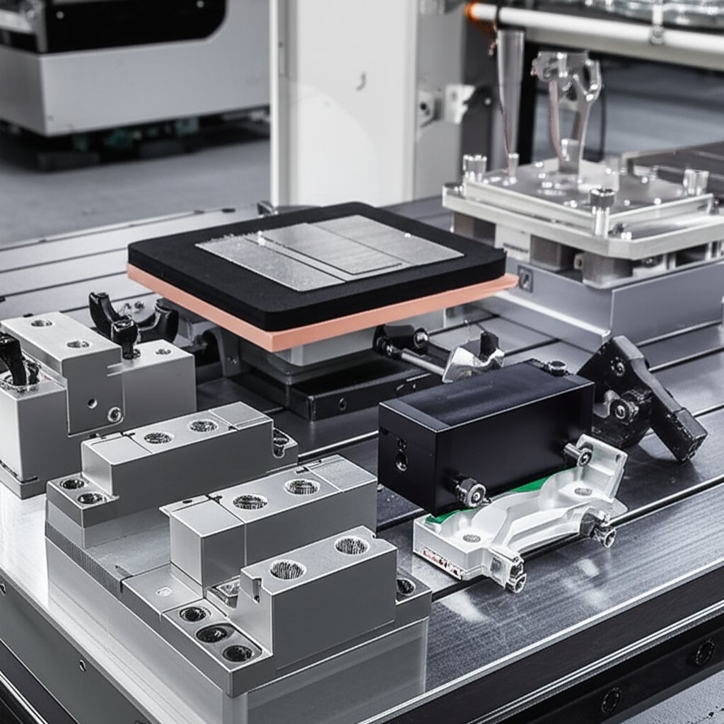
Workholding Methods for Accurate Aluminium Parts
When you’re machining aluminium prototypes, how you hold the part is just as important as how you cut it. Ever had a thin plate bow or a delicate feature vibrate under the spindle? That’s why mastering workholding is a must for anyone aiming to produce precise cnc machined products or milled parts. Let’s explore practical strategies that help you avoid scrap and deliver consistent results—whether you’re working with a chunky block of aluminum for cnc or a wafer-thin panel.
Soft Jaws and Datum Strategy for Prismatic Parts
For most prismatic aluminium parts (think brackets, housings, or jigs), a vise with custom soft jaws is a go-to solution. Soft jaws—machined from aluminum or plastic—conform to your part’s shape, providing gentle but firm grip without marring the surface. Here’s how to get the most out of them:
- Machine custom pockets in the jaw faces to match your part’s outline for maximum stability.
- Use dowel pins or locating features in the jaws to establish repeatable datums—this ensures your aluminum for cnc parts are always referenced from the same point, reducing setup time and errors.
- Plan your primary and secondary operations so each setup references a reliable datum, minimizing cumulative error.
Pros
- Excellent repeatability for batch runs
- Protects delicate surfaces from vise marks
- Quick changeover for similar parts
Cons
- Less effective for irregular or very thin parts
- Requires time to machine each custom jaw set
Vacuum, Glue, and Sacrificial Fixtures for Thin Plates
Machining thin aluminium sheets or panels? Traditional clamping can distort or even crush the workpiece. Instead, consider:
- Vacuum chucks: Use atmospheric pressure to hold large, flat parts evenly—great for minimizing distortion, but best for parts with enough surface area.
- Adhesive workholding: Double-sided tape or specialized glues secure thin pieces for light machining. Easy to set up, but typically limited to small or medium-sized parts.
- Sacrificial plates: Attach your part to a flat plate (using screws, tabs, or adhesives), then machine features or profiles while keeping the part flat. After machining, separate the part from the plate.
Pros
- Minimizes risk of bowing or vibration in thin sections
- Allows access to nearly all surfaces
- Ideal for prototypes where finish and flatness are critical
Cons
- Vacuum fixtures require a reliable seal and are less effective for small parts
- Adhesive methods may leave residue or be difficult to remove
- Sacrificial plates add an extra separation step
Preventing Distortion and Pull-up in Finishing Passes
Aluminium’s low stiffness means even minor clamping or cutting forces can cause distortion—especially in thin-walled or intricate cnc milled parts. To keep everything in spec:
- Balance clamping pressure—tight enough to hold, but not so tight you deform the part.
- Leave uniform stock for finishing passes to maintain support until the final cut.
- Minimize tool overhang to reduce vibration and improve surface finish.
- Consider using tabs, peelable wax, or low-melt alloys to support fragile features during machining, then remove them after.
- Use rest machining strategies in your CAM software to avoid spring-in or spring-back during final cuts.
| Fixture Type | Best-Fit Geometries | Risks/Considerations |
|---|---|---|
| Soft Jaws | Prismatic, repeatable shapes, medium-thick parts | Setup time, not ideal for thin plates |
| Vacuum Chuck | Large, flat, thin sheets or panels | Seal integrity, limited holding force on small parts |
| Adhesive/Tape | Small, thin, flat parts; prototypes | Residue removal, limited holding strength |
| Sacrificial Plate | Parts needing full edge access or complex profiles | Extra separation step, material waste |
Whether you’re holding a robust block of aluminum for cnc or a fragile panel, the right fixture makes all the difference for aluminum parts machining. Don’t forget: photograph your setups and jot down lessons learned—each project helps you refine your approach for the next [source].
With solid workholding in place, you’re ready to ensure tight tolerances and reliable inspection—next, we’ll show how to link fixturing choices to smarter QA and GD&T decisions for your cnc aluminium prototyping workflow.
Inspection and GD&T for CNC Aluminium Prototyping
Ever wondered why two seemingly identical aluminium prototypes can behave differently in assembly? The answer often lies in how tolerances and inspection are handled. In CNC aluminium prototyping, setting the right expectations for accuracy and quality is just as important as clever design or machining strategy. Let’s break down how to use tolerances, datums, and GD&T to ensure your machined prototypes work the first time—without driving up costs or timelines.
Picking Reasonable Prototype Tolerances
Sounds complicated? Actually, it starts with a simple question: What does this feature need to do? For most cnc machined prototypes, tolerances should be tight only where function or fit demands it—like mating holes, bearing bores, or sealing faces. For non-critical areas, looser bands keep machining and inspection fast and affordable. Industry standards such as ASME Y14.5 or ISO 1101 provide guidance, but always tailor your approach to the prototype’s end use.
For example, protolabs tolerances are often used as a reference for default bands in rapid prototyping. While these are a good starting point, don’t over-constrain unless absolutely necessary. Overly tight tolerances can lead to higher costs, longer lead times, and unnecessary scrap [source].
Datum Schemes That Make Machining and Inspection Easier
Imagine trying to measure a part with no clear reference—confusing, right? That’s why a clear datum scheme is essential. A datum is a physical feature (like a face or hole) that serves as a reference for all other measurements. By establishing primary, secondary, and tertiary datums, you make both machining and inspection more reliable and repeatable.
- Primary datum: The main surface or feature that locates the part in space
- Secondary datum: A second feature that orients the part
- Tertiary datum: A third feature that locks the final axis
Good datum selection simplifies setups for cnc machining aluminium and ensures inspectors can check parts efficiently, reducing ambiguity and rework.
GD&T Callouts That Add Clarity Without Overconstraining
Ever seen a drawing loaded with mysterious symbols? That’s GD&T (Geometric Dimensioning and Tolerancing)—the language that defines exactly how a part should fit and function. Instead of just stating dimensions, GD&T uses symbols to specify allowable variations in form, orientation, and location. This removes guesswork and aligns everyone from designer to machinist to inspector.
Example: “Hole pattern: ⌀ callout with positional tolerance to datum A|B|C”
Example: “Shaft: diameter with runout to datum A”
Use GD&T where it matters most—on features that affect assembly, movement, or sealing. For simple shapes or non-critical areas, stick with basic linear tolerances. Remember: every extra symbol adds inspection time and cost, so apply them with purpose.
Inspection Checkpoints and Tools for Common Features
Inspection isn’t just a final hurdle—it’s a feedback loop that keeps your machined aluminium parts on track. A robust inspection plan covers key stages:
- First-off inspection: Check the first part off the machine for critical dimensions and features.
- In-process checks: Spot-check during production to catch drift or tool wear.
- Final inspection: Verify all critical-to-function features before delivery.
For high-precision prototyping services, these checkpoints are non-negotiable. But what tools do you need?
- Calipers and micrometers for basic external and internal measurements
- Pin gauges or bore gauges for holes and bores
- Thread gauges for internal and external threads
- Height gauges and surface plates for flatness and parallelism
- Coordinate Measuring Machine (CMM) for complex geometries or tight tolerance features
For cnc machined part inspection, always match the tool to the tolerance required—no need to use a CMM for a feature with a wide tolerance band.
Takeaway: The best CNC aluminium prototyping results come from balancing tight tolerances where they matter and staying flexible elsewhere. Use datums and GD&T to clarify intent, and back it up with staged inspection—so your prototypes fit, function, and move you closer to production.
With your tolerances and inspection plan set, you’re ready to move from digital design to physical part—next, we’ll explore how to streamline the workflow from CAD to first article for even faster, more reliable prototyping.
Streamlined Workflow for Rapid CNC Aluminium Prototyping
Ever felt lost between your CAD model and a physical prototype in hand? You’re not alone. The journey from digital design to a testable aluminium part can seem overwhelming, but a clear, step-by-step workflow makes all the difference. With the right process, you’ll minimize surprises, compress iteration cycles, and get the most from your cnc aluminium prototyping budget.
From CAD and DFM to Setup Sheets
It all starts with a well-prepared CAD model. But before you hit “run” on the prototype machine, take time for a Design for Machining (DFM) review. This means checking for features that are hard to cut, confirming material specs, and making sure tolerances are realistic for rapid cnc machining. Once the design is sound, hand it off to CAM (Computer-Aided Manufacturing) to generate toolpaths and select strategies tailored to aluminium—think optimal feeds, speeds, and cutter choices for your cnc machining prototype.
Don’t forget the essentials: a clear fixture plan, a complete tool list, and detailed setup sheets. These documents guide the machinist through each operation, reducing the risk of missing a step or misinterpreting the design.
Program Prove-Out and Safe First Cuts
Before any metal chips fly, simulate your program in CAM software to catch collisions or inefficiencies. A dry run or “air cut” on the actual machine—running the program without touching the part—helps verify tool movements and workholding. This step is crucial for avoiding costly mistakes, especially with complex geometries or unfamiliar setups in sample machining.
First Article Review and Iteration
Once the first part comes off the machine, it’s time for a thorough inspection. Compare critical dimensions and features to the drawing or model, focusing on those that impact fit, function, or downstream assembly. Document any deviations, nonconformances, or lessons learned. If something’s off, update your CAD/CAM files and try again. This feedback loop is at the heart of rapid cnc prototyping—every iteration brings you closer to the perfect part.
Capturing Lessons for Revision Control
Imagine finding the same error on the next batch because no one logged the fix. To avoid this, document every change, nonconformance, and engineering change order (ECO). Good revision control means your team learns from each cycle, speeding up future projects and ensuring consistent quality across all cnc machining capabilities.
- DFM review of CAD for machinability, material, and tolerances
- CAM programming and toolpath generation
- Fixture planning and tool list creation
- Setup sheet preparation
- Simulation and program prove-out (dry run/air cut)
- First-off part machining and inspection
- Feedback, documentation, and revision updates
| Workflow Step | Key Deliverables | Stakeholders |
|---|---|---|
| DFM Review | DFM report, design notes | Engineer, machinist |
| CAM Programming | CAM file, toolpaths | CAM programmer |
| Fixture & Tool List | Fixture plan, tool list | Machinist, setup tech |
| Setup Sheets | Operation instructions | Machinist |
| Simulation & Dry Run | Simulation report, dry run signoff | Machinist, QA |
| First-Off Inspection | Inspection report, sample machining notes | QA, engineer |
| Feedback & Revision | Revision log, ECO notes | All team members |
Key Insight: Measure what matters. Focus your inspection and documentation on features that impact function or downstream steps—don’t get bogged down in non-critical details.
By following this workflow, you’ll notice fewer surprises and more predictable results in your cnc aluminium prototyping projects. With each iteration, your process becomes smoother, your team learns faster, and your prototypes move closer to production-ready quality. Up next, let’s tackle common troubleshooting tips to keep your projects on track when things don’t go as planned.

Troubleshooting Aluminium CNC Milling
Ever watched an aluminum prototype come off the machine with unexpected milling marks, burrs, or even warping? If so, you’re not alone. Even the best setups in cnc aluminium prototyping can run into issues—especially when pushing for speed or complex features. Here’s how to spot, diagnose, and fix the most common problems in cnc machining aluminum without endless trial and error.
Fixing Chatter, Vibration, and Poor Surface Finish
Chatter—those wavy lines or ripples on your part—signals vibration between tool and material. It’s a top culprit behind inconsistent finishes in aluminum milling cnc machine work. You’ll often see this when cutting thin walls, using long tools, or running aggressive feeds. To address it:
- Check tool overhang: Keep cutters as short as possible for rigidity.
- Increase tool diameter for added stiffness when the feature size allows.
- Refine tool engagement: Use lighter cuts or split deep pockets into multiple passes.
- Verify workholding: Make sure the part is clamped securely, especially if it’s thin or tall.
- Prefer climb milling for smoother cuts and less vibration.
Imagine machining a thin bracket and hearing a high-pitched squeal—shortening the tool and tightening the clamp often results in a much cleaner cut and fewer milling marks.
Eliminating Burrs and Chip Welding
Burrs—those sharp, unwanted edges—are common in fabricating aluminum. They can impact fit, safety, and downstream assembly. What causes them?
- Dull tools that push rather than cut the milling material.
- Poor chip evacuation, causing chips to get re-cut or welded onto the surface.
- Low feed rates, resulting in rubbing instead of clean shearing.
To minimize burrs and chip welding in cnc metal milling:
- Always use sharp, well-maintained cutters.
- Maintain feed rates high enough to form chips—not dust or ribbons.
- Plan a deburr step: manually (file, abrasive) or with a chamfer toolpath in CAM.
- Use coolant or Minimum Quantity Lubrication (MQL) to reduce chip adhesion.
- Optimize tool geometry—polished flutes and higher helix end mills can help prevent built-up edge and chip sticking.
When you see built-up edge or sticky chips, a quick tool change or coolant adjustment can prevent hours of post-processing.
Preventing Distortion and Warping in Thin Parts
Aluminum’s low modulus means thin sections are prone to distortion—especially after aggressive machining or when releasing from a fixture. You’ll notice this most on large panels or delicate features. Here’s how to keep your aluminum milling cnc machine work flat and true:
- Balance material removal across both sides to reduce internal stress.
- Leave extra stock for finishing passes, so the part stays supported until the final cut.
- Use vacuum or adhesive fixtures to distribute clamping force evenly.
- Allow parts to "rest" between roughing and finishing to relieve stress.
- Consider stress-relief cycles for critical prototypes.
Imagine machining a thin cover plate—roughing both sides before finishing the final profile can help prevent the dreaded “potato chip” effect.
| Symptom | Likely Cause | Corrective Action |
|---|---|---|
| Chatter / Wavy Marks | Tool overhang, weak fixturing, aggressive cuts | Shorten tool, improve clamping, lighten cuts, use climb milling |
| Burrs on Edges | Dull tools, low feed, poor chip evacuation | Sharpen/change tool, increase feed, deburr, optimize chip removal |
| Chip Welding / Built-Up Edge | Sticky chips, low speed/feed, poor coolant | Increase speed/feed, improve coolant/MQL, use polished/high-helix tools |
| Distortion / Warping | Unbalanced machining, thin features, stress release | Balance cuts, use rest machining, vacuum/adhesive fixture, stress relief |
| Swirl or Tool Marks | Incorrect feed/speed, chip recutting | Adjust parameters, improve chip evacuation, simulate toolpaths |
| Incomplete Cuts | Dull tool, poor fixturing, wrong toolpath | Change tool, check fixture, review CAM strategy |
Tip: Change one variable at a time and document the outcome. This methodical approach helps you zero in on the root cause faster and builds a troubleshooting playbook for future cnc machining aluminum projects.
By understanding these common pitfalls and quick fixes, you’ll improve the quality and reliability of your cnc aluminium prototyping—and spend less time reworking parts. Next, let’s look at how cost and RFQ strategies can further streamline your prototyping workflow.
Cost Drivers and RFQ Checklist for Faster Quotes in CNC Aluminium Prototyping
Ever sent out a request for a CNC aluminium prototype and waited days for a quote—only to find it was way over budget? You’re not alone. Knowing what drives cost and lead time, and what to include in your RFQ package, can make the difference between a smooth project and endless back-and-forth. Let’s break down the essentials so you get accurate, timely quotes for your prototype machining needs.
Major Cost and Lead-Time Drivers
Imagine you’re designing a custom aluminum part. What makes the price go up or down? It’s not just the size or shape. Here are the main factors that influence the cost and delivery of cnc prototype and rapid prototyping cnc machining projects:
- Material grade and availability: Higher-grade or specialty alloys cost more and may have longer lead times. Aluminum is generally cost-effective, but rare tempers or oversized billets increase expense.
- Design complexity: Intricate features, undercuts, or deep pockets require more machine time and may need advanced setups.
- Part size and stock removal: Larger parts and those requiring lots of material to be cut away (high stock removal) drive up both material and machining costs.
- Number of setups: Each time a part is repositioned, it adds programming and labor time. Multi-sided or multi-operation parts cost more.
- Fixture complexity: Custom fixtures or jigs for holding irregular shapes increase both lead time and cost.
- Tolerances and inspection: Tighter tolerances and higher inspection standards require more skilled labor and advanced metrology.
- Surface finishes: Anodizing, powder coating, or polishing add steps and cost. Choose finishes based on function, not just appearance.
- Thread types and features: Uncommon thread forms, deep threads, or special inserts add to the machining cycle.
- Batch size: One-off prototypes have higher per-part costs due to setup and programming. Batch production spreads those costs across more units, reducing the price per part.
Understanding these drivers helps you prioritize what matters most for your prototype machining services—and where you can trim costs without sacrificing quality.
What to Include in Your RFQ Package
Ever wonder why some prototype cnc machining quotes come back quickly and others take forever? It usually comes down to the completeness of your RFQ (Request for Quotation). A clear, detailed package eliminates guesswork for vendors, speeds up quoting, and reduces the risk of surprises later. Here’s what to include:
- 3D CAD model and PDF drawing (with all dimensions and tolerances clearly marked)
- Material specification (grade and temper, e.g., 6061-T6 aluminum)
- Surface finish requirements (e.g., anodized, bead blasted, as-machined)
- Critical-to-quality notes (features that affect fit, function, or assembly)
- Geometric Dimensioning & Tolerancing (GD&T) if needed
- Thread callouts and assembly instructions (if applicable)
- Batch quantity and target delivery date
- Inspection requirements (standard vs. advanced, e.g., CMM report)
- Packing and labeling preferences (bulk or retail, special packaging if needed)
- Contact information for technical questions
Providing this information up front helps vendors specializing in metal milling services or aluminum parts assembly service quote accurately and quickly. It also reduces the risk of miscommunication or costly revisions down the road.
Strategies to Reduce Price Without Sacrificing Function
Want to keep your custom aluminum parts project on budget? Sometimes small changes make a big difference. Here are proven levers to pull for cost-effective rapid prototyping cnc machining:
- Relax non-critical tolerances—tighten only where function or fit demands it.
- Combine setups—design parts so more features can be machined in a single clamping.
- Standardize hole sizes to match common end mill diameters—reduces tool changes and cycle time.
- Choose finishes compatible with your alloy—avoid high-cost treatments unless they’re essential.
- Minimize deep pockets or thin walls—these are harder to machine and often require slower feeds.
- Order in batches if possible—spreads setup costs over more units.
- Ask about alternative alloys or machining processes that might be more cost-effective for your needs.
By following these strategies, you’ll notice faster quotes, fewer clarifications, and more predictable costs in your next cnc aluminium prototyping project.
With a well-prepared RFQ and a clear understanding of cost drivers, you’re ready to move confidently toward production. Next, let’s see how to scale from prototype to pilot runs and choose the right partner for ongoing success.

Scale Prototypes to Production with the Right CNC Manufacturing Partner
Ready to move beyond one-off CNC aluminium prototypes and scale up to pilot runs or full production? It’s a big leap—and the right approach can make or break your project’s success. Imagine you’ve nailed your prototype: fit, finish, and function are spot on. But what happens when you need ten, a hundred, or even a thousand parts—all consistent, all on time? Let’s explore how to bridge that gap, tighten controls, and select a partner who can deliver at every stage.
When to Tighten Tolerances and How to Document Changes
As you shift from prototyping to production, you’ll notice that tolerance requirements often change. Early prototypes are about speed and function—tolerances are kept as loose as possible for quick iterations. But for pilot and production runs, it’s time to revisit every critical feature. Ask: Where did issues show up in testing? Which dimensions impacted assembly or downstream processes?
- Functional testing reveals weak points: Use test data to identify which features need tighter control. For example, if a bore was too loose for a bearing, tighten that tolerance for the next batch.
- Document every change: Log updates in your CAD and drawing revisions. Clear documentation ensures your team and vendors are always working from the latest version, supporting repeatability in aluminum parts manufacturing.
- Prepare for process capability checks: As volume grows, statistical tools like Cp/Cpk help confirm that your process can consistently hit those new, tighter specs.
Imagine running a batch of custom aluminum machining parts and discovering a recurring variance—by documenting and tightening that dimension, you set the foundation for reliable production.
Fixture, Process, and Inspection Upgrades for Repeatability
Scaling up means more than just making more parts—it’s about making every part the same, every time. Here’s how to boost repeatability as you move from rapid prototyping cnc to higher volumes:
- Dedicated fixtures: Invest in purpose-built fixtures or jigs for critical features. These minimize variation from setup to setup, especially important for cnc turning & milling operations.
- Poke-yoke (mistake-proofing): Add features that prevent incorrect loading or orientation, reducing operator errors.
- Robust inspection plans: Move from basic first-off checks to in-process and final inspections using CMMs or automated gauges. This is crucial for parts destined for aluminum prototype assemblies or where aluminium cnc service providers must guarantee precision.
- Process monitoring: Track key metrics—tool wear, temperature, humidity—to catch drifts before they cause scrap.
With these upgrades, you’ll notice fewer surprises and more consistent results—whether you’re making five or five hundred parts.
Choosing a Rapid Prototyping Partner That Scales
Not all cnc manufacturing services are created equal. When it’s time to move from prototype to production, the right partner will make scaling seamless. Here’s what to look for:
| Service Criteria | XTJ Rapid Prototyping Services | Other Providers |
|---|---|---|
| Processes Supported | CNC Machining, CNC Turning & Milling, Injection Molding, Die Casting, Prototype Aluminum Casting | Varies—often limited to one or two processes |
| Aluminum Alloys On-Hand | 50+ materials, including 6061, 7075, and more | Limited selection—may require custom sourcing |
| DFM (Design for Manufacturability) Feedback | Complimentary, engineer-driven feedback for every project | Often extra cost or less comprehensive |
| Quality Certifications | ISO 9001:2015 certified | Varies; some lack formal certifications |
| Turnaround Time | Rapid—optimized for both prototypes and pilot runs | Can be slower, especially for scaling volumes |
| Complementary Services | Bridges to molding, die casting, and pilot production | Usually limited; may require multiple vendors |
| Industry Applications | Aerospace, medical, automotive, electronics, and more | May be specialized or limited in scope |
For projects demanding a seamless transition from one-off prototypes to pilot or full production, XTJ’s Rapid Prototyping Services stand out. With advanced CNC machining, die casting, and even prototype aluminum casting, they cover every stage. Their experienced engineers provide DFM feedback as standard, and a wide aluminum alloy inventory means less waiting and more flexibility. Add ISO 9001:2015 certification, and you get reliable quality whether you need a handful of parts or a production run.
Takeaway: When scaling CNC aluminium prototyping, prioritize partners who offer broad process capabilities, robust DFM support, certified quality, and a track record of scaling from prototype to production. This ensures your aluminum prototype becomes a reliable, repeatable product—no matter the volume.
By focusing on these strategies, you’ll bridge the gap from concept to production with confidence—ready to deliver consistent, high-quality results for every stage of your project.
CNC Aluminium Prototyping: Frequently Asked Questions
1. How much does it cost to CNC aluminum?
The cost to CNC machine aluminum varies based on part complexity, alloy choice, and batch size. Factors like material grade, design intricacy, required tolerances, and surface finish all influence the final price. Providing a complete RFQ package with clear drawings and requirements helps vendors give accurate, competitive quotes for your project.
2. What materials cannot be CNC machined?
Materials that cannot be CNC machined include soft rubbers, flexible polymers, certain composites, ceramics, and some types of glass. For CNC aluminium prototyping, standard aluminum alloys like 6061 and 7075 are ideal, while highly flexible or brittle materials may require alternative manufacturing methods.
3. What are the main benefits of CNC aluminium prototyping over 3D printing or casting?
CNC aluminium prototyping offers superior dimensional accuracy, real alloy properties, and professional surface finishes compared to 3D printing. Unlike casting, CNC does not require expensive tooling, making it ideal for rapid iterations, functional testing, and small batches without long lead times.
4. How do I choose the right aluminum alloy for CNC prototyping?
Select the alloy based on your prototype's needs: 6061-T6 is versatile and easy to machine, 7075-T6 provides higher strength, and 5052 or 5083 excel in corrosion resistance and formability. Consider machinability, finish quality, and the intended use to ensure optimal results.
5. What should be included in an RFQ for CNC aluminium prototypes?
A complete RFQ should have a 3D CAD model, detailed drawing with tolerances, specified alloy and temper, finish requirements, batch quantity, inspection needs, and any assembly or packaging instructions. This ensures fast, accurate quotes and smooth project execution.
-
Posted in
aluminum machining, CNC aluminium prototyping, CNC machining workflow, prototype cost drivers, rapid prototyping