
The 5 Most Common Defects in Aluminum Alloy CNC Machining (with Solutions)
Having handled over 1,200 drawings and 237 complaints, we found that the following five types of defects account for 83% of rework and scrap.
The solution isn’t simply to “increase the coolant flow.”
Article Outline
Introduction
Defect 1: Tool Sticking and Chip Buildup
Defect 2: Post-Machining Deformation
Defect 3: Stripped Threads / Abnormal Gauge Readings
Defect 4: Black Lines and Color Variation After Anodizing
Defect 5: Microcracks/Edge Chipping
Checklist + Conclusion
Introduction
Aluminum alloys require low cutting forces and are easy to chip, but precisely because they are “easy to machine,” defects rarely seen in steel parts often occur: dimensional changes after machining, dark streaks after anodizing, and stripped threads. The root cause lies not in machine tool accuracy, but in a lack of understanding of aluminum’s properties.
Defect 1: Tool Adhesion and Build-Up of Edge (BUE) (BUE)
Symptoms: Scaly surface irregularities; aluminum deposits fused to the tool; drastic reduction in tool life.
Root Causes: Mismatched cutting speed and feed rate + Improper tool rake angle + Insufficient coolant concentration or pressure.
Countermeasures
High-speed, shallow cutting: Linear speed ≥ 800 m/min, cutting depth 0.05–0.1 mm.
Use aluminum-specific polished-groove or DLC-coated tools.
Maintain coolant concentration at 7%–10% (lubrication drops sharply below 5%).
For deep holes or cavities, switch to minimal quantity lubrication (MQL) or high-pressure internal cooling.
Defect 2: Post-machining deformation
Symptoms: Dimensional deviation in thin-walled parts after releasing from fixtures, warping in long components, or failure upon re-inspection the next day (stress release).
Root Cause: Clamping stress + residual cutting heat stress + initial internal stress in the material.
Countermeasures
Separate roughing and finishing: Release the fixture after roughing and allow natural aging for 4–8 hours before finishing.
Modify clamping to use vacuum chucks or soft jaws + stop blocks to avoid over-clamping in the vise.
Use helical feed and dynamic milling in programming to avoid impact.
Require suppliers to provide stress-relief annealing (300°C × 2h).
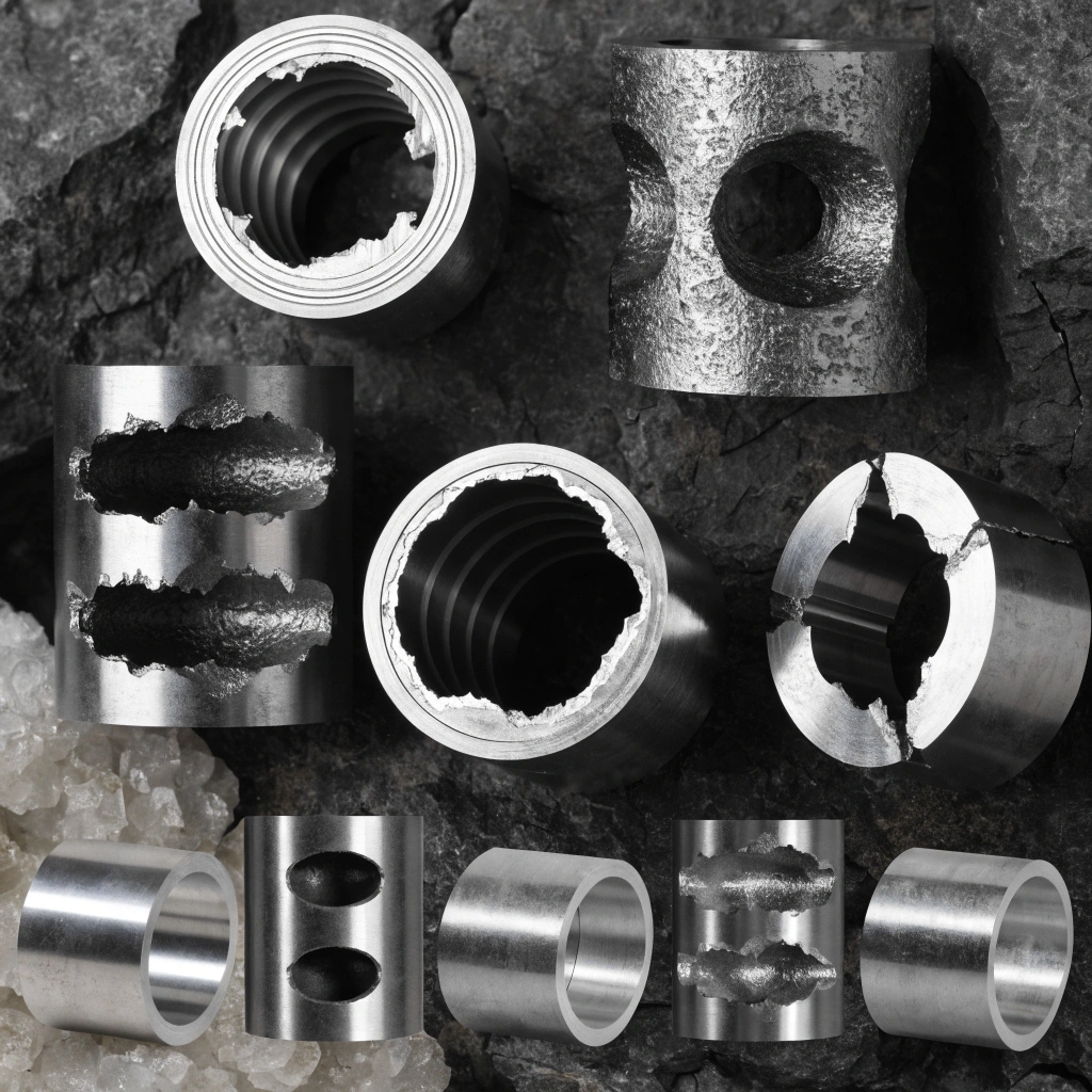
Defect 3: Stripped threads or abnormal go/no-go gauges
Symptoms: Abnormal tightness/looseness during tapping; the go gauge fails to enter, or the no-go gauge passes; the threads slip during assembly.
True cause: Pilot hole deviation + poor chip evacuation + excessive tapping speed + failure to use thread inserts.
Countermeasures
Strictly adhere to the upper limit of the pilot hole range specified in the standard (e.g., 4.25–4.3 mm for M5).
For blind holes, switch to a form tap (no chips, high thread strength).
When the thread depth exceeds 1.5 times the diameter, pre-install a steel thread insert or self-tapping insert.
After tapping, blow out chips with an air gun and re-inspect with a thread gauge.

Defect 4: Dark Lines, White Spots, and Color Variation After Anodizing
Symptoms: Dark streaks, blackening, or color variation between batches appear after anodizing; these were not visible during machining.
Root Causes: Residual cutting fluid + uneven surface work-hardening layer + material composition segregation.
Countermeasures: Use an emulsifier specifically designed for aluminum alloys; after machining, rinse with ultrasonic cleaning and hot water (above 60°C).
Allow 0.05–0.1 mm for finishing during the “pre-anodizing finishing” process to remove the cold-work layer.
Require the anodizing plant to follow Grade II sulfuric acid anodizing standards + sealing treatment; conduct small-scale trials first.
Prioritize 6061/5052 alloys; avoid mixed-alloy aluminum.
Defect 5: Microcracks or Edge Chipping
Symptoms: Fine notches on edges; cracks visible via penetrant testing; early failure in fatigue testing.
Root Causes: Continuing machining with worn tools + excessive feed rate + improper tool retraction + failure to deburr.
Countermeasures
Inspect the cutting edges of finishing tools every 100 parts or 2 hours; replace if wear exceeds 0.2 mm.
Program a 0.2mm chamfering path or use a round-nose tool to smooth the edges.
Use arcs for tool entry and exit during retraction; avoid vertical tool lifting.
Perform initial-piece penetrant testing for aerospace/medical parts.
Appendix: Defect Prevention Checklist (May be posted near the machine)
Pre-processing Defect Types During Processing Post-processing
Tool Adhesion Coolant Concentration ≥7% Silver-white Chips Inspect First Piece
Surface Deformation Confirm Stress Condition Separate Rough and Finish Machining Operations; Loosen Fixture in Intermediate Stage Re-measure After Laying Flat for 24 Hours Threads Verify Guide Hole Diameter Remove Blind Hole Notches Every 3 Holes Record Feasible/Infeasible Measurement Results
Oxidation Color Variation Chlorine-free coolant Ultrasonic cleaning after finishing Test oxidation on small samples Microcracks Inspect tool rake face Avoid vertical retraction when retracting the tool Visual inspection of edges + random sampling


)