
Rapid Prototype Aluminium Casting: Slash Lead Time And Cost

Prototype Aluminium Casting
Ever wondered why some teams launch successful products faster and with fewer surprises? Often, the answer lies in how they approach prototyping—especially when the goal is to test real-world function, not just form. If you’re designing parts that need cast-like geometry, internal passages, or realistic heat transfer, prototype aluminium casting can be the difference between a smooth production ramp and costly late-stage changes.
What prototype aluminium casting means
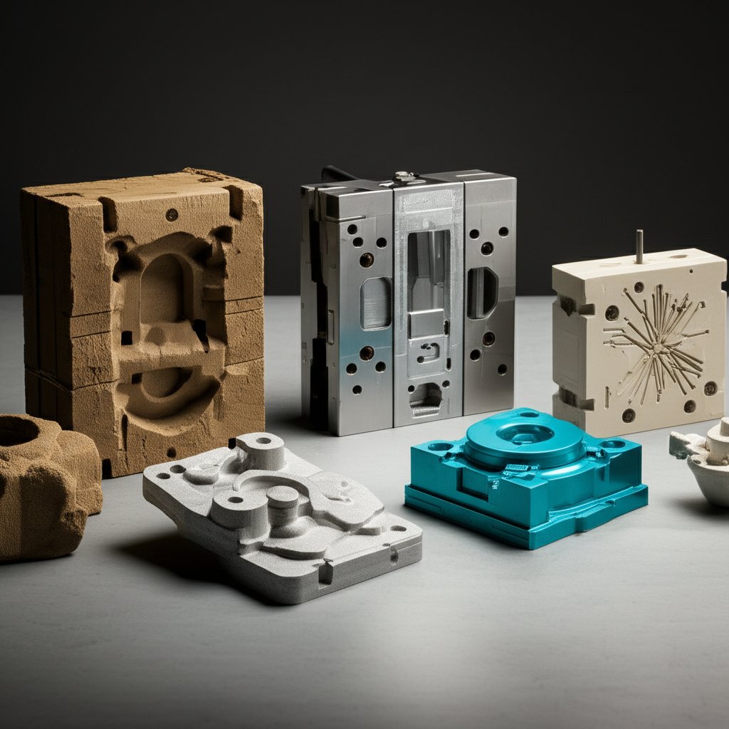
Prototype aluminium casting refers to the rapid creation of functional, cast-aluminum parts for early design validation. Unlike mass production casting, which relies on hard tooling and optimized process controls, prototype casting leverages temporary or soft tooling—think sand molds, 3D-printed patterns, or machined dies—to produce a handful of parts quickly and cost-effectively. This approach lets you:
- Validate geometry and manufacturability before committing to expensive production tools
- Check assembly fit and interface compatibility in real assemblies
- Assess thermal and mechanical performance in conditions close to the final use case
Aluminum’s combination of low density, high strength, and excellent thermal properties makes it ideal for producing lightweight, durable prototypes that behave like production parts.
Key terminology and process types
- Prototype: Early-stage part for design validation—not for sale or end use
- Pilot: Limited batch for process tuning and assembly testing
- Bridge: Short-run production bridging between prototype and full-scale launch
- Sand casting: Flexible, low-cost molds for quick iteration
- Permanant mold casting: Reusable metal molds for improved repeatability
- Die casting: High-speed, precision process—best for higher prototype volumes
- Investment casting: Sacrificial patterns for fine detail and complex shapes
When to choose cast prototypes over CNC
Sounds complex? Imagine you’re deciding between prototype casting and cnc aluminium prototyping. Here’s a simple decision prompt:
- If your part has internal cavities, near-net shape geometry, or you need to validate cast microstructure and properties, prioritize a cast prototype.
- If you only need the external form, a short-run fixture, or a quick geometry check, CNC machining is often faster and more precise.
Remember, casting excels at replicating production-like features that CNC can’t easily achieve—especially for parts with complex internal channels or cooling passages.
Advantages and trade-offs you should know
- Speed: Temporary or rapid tooling slashes lead time compared to production molds
- Cost: Lower upfront investment for short runs, but per-part cost is higher than mass production
- Flexibility: Easy to iterate designs and test multiple variants
- Limitations: Surface finish may be rougher; dimensional variability is higher than production casting; post-processing (machining, finishing) may be needed
- Process controls: Gating and riser design are crucial to minimize defects like porosity or shrinkage—especially in prototypes where process optimization is limited
Key Takeaway: Prototype aluminium casting helps you balance speed, cost, and technical risk. It’s your best bet when you need cast-like properties and geometry—long before full-scale production tools are ready.
As you move forward, you’ll see how process selection, alloy choice, and design-for-casting rules all impact the efficiency of your prototyping workflow. Next up: a side-by-side comparison of casting methods, a guide to picking the right alloy, and practical DfC templates to help you move from concept to quote-ready package—fast and with confidence.
Want to dive deeper into how aluminum prototype processes work? Check out this detailed guide on aluminum prototype processes.
Choose the right casting process for your aluminum prototypes
Match your goals to the right casting process
When it comes to prototype aluminium casting, the route you choose can make or break your project timeline, accuracy, and budget. Imagine you need a handful of parts to validate a new design. Do you pick sand casting for speed and flexibility, or is investment casting’s finer detail worth the wait? Let’s break down the main processes so you can match your goals—whether that’s geometry validation, mechanical property realism, or cosmetic assessment—to the best-fit method.
| Process | Typical Lead Time | Tolerance Bands | Surface Finish | Internal Feature Complexity | Unit Cost (Low Qty) | Engineering Change Flexibility |
|---|---|---|---|---|---|---|
| Sand Casting | Short to moderate (2–6 weeks for samples) | Coarse (+/-0.030” to 6”) | Coarse (6.3–12.5 µm) | Good for simple to moderate cores | Low tooling, moderate part cost | Very high—easy to modify patterns |
| Permanent Mold | Moderate to long (12–15 weeks for samples) | Moderate (+/-0.015” to 1”) | Moderate (3.2–10 µm) | Limited—best for simpler cavities | Higher tooling, lower unit cost at volume | Low—hard tooling, changes are costly |
| Die Casting | Long (12–15 weeks for samples, but fastest cycle times after tooling) | Fine (+/-0.002” per inch) | Fine (0.8–1.6 µm) | Good for complex, thin-walled parts | High tooling, low per-part cost at volume | Very low—tool changes are expensive |
| Investment Casting | Long (8–10 weeks for samples) | Fine (+/-0.003” to 0.125”) | Fine (1.6–3.2 µm) | Excellent—best for intricate shapes and thin sections | Moderate tooling, higher per-part cost | Moderate—pattern changes easier than die, harder than sand |
| Rapid Patterns / Aluminum Rapid Tooling | Very short (as little as 3 weeks for samples) | Varies—depends on base process | Varies—depends on base process | Good for quick iteration, moderate complexity | Low to moderate tooling, higher per-part cost | Very high—patterns can be quickly reprinted or machined |
How pattern and tooling choices affect speed
Ever wonder why some teams have prototype parts in hand while others are still waiting on tooling? The secret is in the pattern and tooling approach. For example, aluminum rapid tooling and 3D-printed patterns let you skip long lead times and easily adapt to design changes. Sand casting patterns are typically the fastest and cheapest to adjust, making them ideal for early-stage cast prototypes. In contrast, die casting and permanent mold require expensive, hardened tooling—best reserved for when your design is nearly locked.
- Sand or rapid patterns: Best for fast, flexible iteration. Perfect for concept checks and early design validation.
- Permanent mold or die casting: Choose these when you need production-like repeatability or are bridging to higher volumes.
Bridging from prototype to pre-production
As your design matures, you may need to transition from rapid, flexible methods to those that mimic production. One practical approach is to cast a near-net shape using sand or investment casting, then finish critical features with CNC machining. This hybrid flow gets you closer to the final part’s geometry and properties without the cost or time of full-scale production tooling. For aluminum die cast prototypes, consider using soft tooling or rapid inserts for short runs—this lets you test out die-cast-like features before committing to expensive steel dies.
Choosing the right casting process is about balancing speed, accuracy, and flexibility. Start with rapid, adaptable methods for early learning, then shift to production-like processes as your design stabilizes and your needs for tolerance and finish increase.
Next, let’s look at how alloy selection impacts not just prototype performance, but also your casting process and post-processing options. Understanding which alloys work best for your goals will help you move seamlessly from prototype to production.
Alloy Selection Without Confusion
How to pick an alloy for your cast prototype
When it comes to prototype aluminium casting, picking the right alloy can feel like a maze. Do you need strength for a load-bearing bracket? Or corrosion resistance for a marine part? Maybe you’re after easy machinability for post-cast finishing. Each goal points to a different alloy—and making the right call early saves time, money, and headaches down the line.
Let’s break down the most common cast alloys you’ll encounter in aluminum prototype work, and how they stack up for prototyping goals:
| Alloy | Strength | Fluidity (Castability) | Heat Treatable | Corrosion Resistance | Machinability | Notes |
|---|---|---|---|---|---|---|
| A356 | Good (can be improved by heat treatment) | Excellent | Yes | Good | Good | Popular for casting prototypes needing a balance of strength and detail |
| 319 | Moderate | Very good | Yes | Moderate | Good | Great for dimensional stability and easy casting; often used in automotive |
| 535 | Moderate | Good | No | Excellent (Mg-based) | Fair | Go-to for marine and chemical environments; less ideal for intricate machining |
| 380 | Moderate | Excellent (especially for die casting) | No | Moderate | Fair | Die-casting favorite—great for thin walls, but more porosity risk |
| 6061 (wrought) | High | N/A (not cast) | Yes | Excellent | Excellent | Typical for CNC-machined aluminium prototypes; rarely used in casting |
| 7075 (wrought) | Very high | N/A (not cast) | Yes | Moderate | Good | Another CNC favorite; not suitable for casting |
Cast vs wrought aluminum in prototyping
Ever wondered why some aluminum prototype parts are cast, while others are machined from solid block? It comes down to the difference between cast and wrought alloys. Cast alloys (like A356, 319, 535, and 380) are formulated for pouring into molds—they flow well and solidify with the right microstructure for complex shapes. Wrought alloys (such as 6061 and 7075) are designed for rolling, extrusion, or forging, and then machined to shape. They’re generally stronger and less porous, but can’t be poured into intricate molds.
- Cast alloys: Best for complex, near-net shapes and internal features. Slightly lower strength, but excellent for realistic casting validation.
- Wrought alloys: Ideal for machined prototypes where precision and mechanical properties are critical, but geometry is simpler.
According to industry guidance, cast alloys offer more shape flexibility and lower cost per pound, while wrought alloys excel in mechanical performance and surface finish.
Property and finishing implications to consider
Here’s where practical choices matter. If your casting prototype will be anodized, remember that different alloys react differently—A356, for example, can yield a clean anodized finish, but porosity must be tightly controlled. Alloys high in silicon (like 380 or LM6) may show more variation in color and surface quality after finishing. For marine or chemical exposure, magnesium-rich alloys like 535 are often preferred for their corrosion resistance.
- Discuss alloy, heat treatment, and post-processing needs with your foundry early—some alloys require special gating or solidification strategies that can impact lead time and cost.
- Think ahead to secondary operations: Will you need to machine critical faces or add inserts? Choose an alloy that machines cleanly and holds tolerances.
- If cosmetic appearance is key, ask for sample finishes and discuss porosity control up front.
Pro tip: The right alloy choice is about more than just mechanical properties. Consider castability, finish, secondary operations, and how the alloy’s chemistry affects both process and performance.
With your alloy options clear, you’re ready to dive into the design rules that help your prototype cast cleanly and efficiently. Next, we’ll explore the geometry guidelines that prevent defects and set you up for a successful casting prototype.
Design Rules That Actually Hold Up
Geometry rules that prevent defects
When you’re developing a prototype aluminum part, a few design tweaks can mean the difference between a clean casting and a costly rework. Sounds complex? Imagine pouring molten metal into a mold—if the geometry isn’t right, you’ll face shrinkage, porosity, or even incomplete fills. To help, here’s a practical table you can use as a design and RFQ reference. Fill in numeric targets with your foundry, referencing standards like the Aluminum Association or ASM Handbook as needed.
| Feature | Recommended Rule | Notes |
|---|---|---|
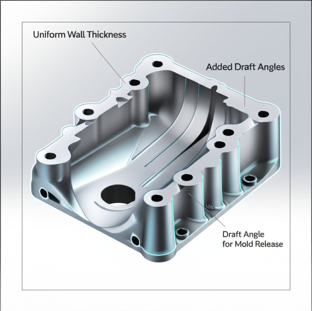
| Wall Thickness | Keep as uniform as practical; avoid abrupt changes | Uniform walls allow better metal flow and solidification; gradual transitions with fillets preferred |
| Draft Angles | Add draft to all as-cast faces | Facilitates easy ejection from the mold; consult supplier for minimum values |
| Fillets & Radii | Use generous fillets at all internal corners | Reduces hot spots and stress risers; improves flow |
| Ribs | Use ribs to stiffen thin walls instead of making walls thicker | Improves stiffness without adding porosity risk or weight |
| Bosses | Hollow out bosses; add fillets at base | Reduces material use and shrinkage; strengthens mounting points |
| Holes & Windows | Maintain sufficient spacing from edges and between holes | Prevents weak sections and casting defects |
| Threads | Prefer external threads for casting; internal threads usually machined | Cast threads are for non-precision fits; precision requires post-machining |
| Cored Passages | Align with main die-pull direction; minimize side-cores | Reduces tooling complexity and cost; improves repeatability |
Designing ribs, bosses, and holes that cast cleanly
Ever noticed how some aluminium castings come out with warping or extra weight? Overly thick walls or poorly designed ribs are often to blame. Instead, use ribs to add strength to thin sections. Hollow out bosses to reduce shrinkage and material cost. For holes, keep them away from edges and from each other to avoid weak zones. And if you need complex cored passages, align them with the main ejection direction to avoid costly side-cores or slides.
- Avoid sharp internal corners—always round them with a fillet
- Transition between thick and thin sections gradually
- Keep wall thicknesses consistent across the part
- Reserve tight tolerances for critical, machined datums
- Limit blind hole depths to what can be reliably cast
Draft, fillets, and machining allowances that save money
Imagine trying to pull a part out of a mold with perfectly vertical sides. You’ll get stuck every time. That’s why adding draft—slight angles to all as-cast faces—is essential. Larger drafts make ejection easier and reduce tool wear, but check with your supplier for the right value for your aluminium prototyping process.
Fillets and radii aren’t just for aesthetics. They help molten metal flow smoothly, reduce stress concentrations, and minimize hot spots that can cause porosity or cracking. As for machining allowance, only add extra stock where you truly need tight tolerances or a fine surface. Too much allowance wastes material and raises cost; too little risks leaving defects or roughness.
- Apply draft to every as-cast face—more for deeper or textured features
- Use fillets on all internal corners, especially at wall intersections
- Add machining allowance only to critical faces, not the entire part
Common mistakes to avoid in prototype aluminum casting
- Sharp internal corners—cause hot spots and voids
- Heavy-to-thin transitions—lead to shrinkage and warping
- Non-uniform wall sections—result in incomplete fill or sink
- Overly tight tolerances across the whole part—increases cost and scrap
- Unclear distinction between as-cast and machined faces—creates RFQ confusion
- Identify functional surfaces and mark as-cast vs. machined faces
- Add draft to all as-cast features
- Round stress risers and sharp corners with fillets
- Equalize wall sections wherever possible
- Plan machining stock only where you need precision
Pro tip: Early DFM reviews with your foundry can reduce rework, porosity, and hot spots—improving both yield and lead time. Always provide a machining model and an as-cast model to avoid ambiguity and streamline quoting.
By following these proven design rules, you’ll set your aluminium prototyping project up for success. Next, we’ll show how to make your RFQ package supplier-ready—ensuring clear communication and fast, accurate quotes for your prototype aluminum casting.
Get Your RFQ Package Right the First Time
CAD and Drawing Prep That Speeds Quotes
Ever sent out a quote request and waited days for a response—only to find out your files or specs were unclear? For aluminum casting projects, disciplined CAD practices and clear separation of as-cast and machined features can slash lead time and avoid costly miscommunication. Imagine a supplier opening your package and instantly seeing exactly what you want: a clean as-cast model, a machining model with color-coded faces, and all the critical details called out. That’s how you get fast, accurate quotes for your cnc aluminum prototype or cast part.
- Include both 3D CAD files (STEP/IGES) and 2D PDFs for each part
- Provide an as-cast model—shows the geometry straight from the mold
- Provide a machining model—highlights faces to be machined, with stock allowances clearly indicated
- Color-code or annotate machined faces and critical surfaces
- Attach a drawing with complete dimensioning, tolerances, and datums (preferably using the 3-2-1 system)
- List material, target alloy, and any acceptable substitutes
- Specify finish and post-processing requirements
- Call out anticipated quantities and required delivery dates
- Highlight any critical-to-quality (CTQ) features or inspection needs
By providing this level of detail up front, you help your supplier quote quickly and accurately, reducing the risk of missed requirements or expensive change orders later.
What to Include in Your RFQ Package
Not sure what files or information your RFQ should contain? Use this checklist to make your next aluminum casting cost estimate as smooth as possible:
| Required Item | Purpose |
|---|---|
| 3D CAD File (as-cast) | Defines the raw casting geometry |
| 3D CAD File (machined) | Shows final geometry, highlights machined faces |
| 2D PDF Drawing | Dimensioning, tolerances, and datums |
| Material & Alloy Spec | Ensures correct metal selection |
| Process Preference | Guides supplier to sand, die, investment, etc. |
| Heat Treatment | Calls out required mechanical properties |
| Finish/Post-Processing | Anodize, chromate, powder coat, etc. |
| Anticipated Quantities | Helps supplier size tooling and price breaks |
| Inspection Requirements | CTQs, NDT, leak tests, etc. |
| Packing/Shipping Details | Bulk or retail, special labeling, etc. |
Specification Text You Can Paste Today
Want to avoid back-and-forth emails? Use these ready-to-go templates—just fill in the blanks with your project details and supplier feedback.
Sample RFQ Email Body
Subject: RFQ – Prototype Aluminium Casting for [Part Name/Number]
Dear [Supplier Name],
Please quote the following prototype aluminium casting project:Please confirm receipt and advise if additional information is required.
- Part Name/Number: [Your Part]
- Anticipated Quantity: [Number of Pieces]
- Material: [e.g., A356, 319, or specified alloy]
- Process: [Sand, die, investment, or supplier recommendation]
- Heat Treatment: [e.g., T6, T51, or none]
- Finish: [e.g., as-cast, anodized, powder coat]
- Inspection: [e.g., dimensional, NDT, leak test]
- Required Delivery: [Date]
- Attached: 3D CAD (as-cast), 3D CAD (machined), 2D PDF drawing
Thank you,
[Your Name/Company]
Drawing Specification Snippet
Material: [A356, 319, or other specified alloy]
Process: [Sand casting, die casting, etc.]
Heat Treatment: [T6, T51, as required]
Finish: [As-cast, anodized, powder coated, etc.]
Inspection: [Dimensional, NDT, CTQ features as noted]
Packaging: [Bulk, individual, special requirements]
Tolerances: [Refer to attached table or as noted]
Note: Supplier to confirm any deviations prior to production.
By standardizing your RFQ and drawing package, you not only improve quote speed and accuracy, but also build trust with your supplier. This disciplined approach pays off in fewer surprises and smoother aluminum casting projects from start to finish.
Ready to move forward? The next section will help you set realistic expectations for tolerances and surface finish—so you can specify what matters, without overburdening your aluminum casting cost or prototype schedule.
Tolerances and Finish That Won’t Blow Budgets
Tolerance and finish by casting process
Ever wondered why your prototype doesn’t fit quite right, or why a part’s surface feels rougher than expected? The answer often lies in understanding aluminum casting tolerances and as-cast surface finish—and how they vary by process. Not all casting methods deliver the same precision or smoothness, and setting the right expectations early can save you both time and cost.
| Process | Typical Tolerance Band | Surface Finish Class | Recommended Machining Stock Allowance | Supplier-Agreed Value |
|---|---|---|---|---|
| Sand Casting | Coarse (loose—best for non-critical fits) | Rough (Ra 6.3–12.5 µm) | Higher (often 2–5 mm) | |
| Permanant Mold | Moderate (better than sand, not as tight as die) | Moderate (Ra 3.2–10 µm) | Medium (1–2 mm typical) | |
| Die Casting | Fine (tight—good for critical interfaces) | Smooth (Ra 0.8–1.6 µm) | Lower (as little as 0.5–1 mm) | |
| Investment Casting | Fine (good for complex, thin-walled parts) | Fine (Ra 1.6–3.2 µm) | Low to medium (1–2 mm typical) |
Where to machine and where to cast
Sounds complex? Imagine trying to hold a ±0.1 mm tolerance across a sand-cast housing—it’s not just tough, it can drive up your costs by 20–50% or more due to special tooling and added rework. The smart move is to specify broader as-cast tolerances for non-critical areas and reserve tight tolerances and fine finishes for a few machined faces.
- Use as-cast surfaces for bulk geometry, non-mating faces, and cosmetic areas where roughness is acceptable.
- Apply machining only to critical datums, sealing surfaces, or features with tight casting GD&T requirements.
- Be intentional with your machining stock allowance—too much wastes time and material, too little risks missing your final dimensions. For aluminum, 0.5–2 mm is typical, but always confirm with your supplier.
Transitioning smoothly to production
When you move from prototype to production, the lessons learned on tolerances and finish are invaluable. You’ll notice that:
- Tighter tolerances call for upgraded tooling, better gating/riser design, and sometimes a shift to a higher-precision process.
- Prototype issues—like unexpected warping or rough surfaces—help you refine your control plan and reduce scrap in production.
- Documenting which faces are machined versus as-cast ensures your production drawings are clear and cost-effective.
-
Reserve these GD&T features for machined datums and critical interfaces:
- Flatness
- Parallelism
- Position (for holes and bosses)
- Profile (for sealing faces)
- Surface finish callouts (Ra, RMS)
Pro tip: “Tight enough to work, loose enough to cast.” Focus your budget and tolerance demands where they matter most, and you’ll get reliable, cost-effective prototype aluminium castings every time.
With realistic tolerances and finish targets in place, you’re ready to tackle the next challenge: understanding what drives lead time and cost—so you can plan for fast, surprise-free prototype delivery.
What to Expect in Prototype Casting Projects
What really drives lead time in prototype aluminium casting?
Ever wondered why some prototype casting projects wrap up in two weeks while others drag on for months? The answer is rarely just one factor. Instead, it’s a blend of decisions and details that shape both your prototype casting lead time and overall cost. Here’s a prioritized look at what truly impacts your schedule:
- Process Selection: Sand casting and rapid tooling methods are typically faster than permanent mold or investment casting, but each has trade-offs in accuracy and finish.
- Pattern/Tooling Approach: Temporary or 3D-printed patterns can be made in days, while CNC-machined dies or hard tooling may take weeks. The choice here is a key driver for tooling lead time aluminum projects.
- Part Geometry: Complex cores, thin sections, or intricate internal features require more advanced molds and longer setup, extending both lead time and cost.
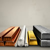
- Alloy Availability: Standard alloys (like A356 or 380) are easy to source and cast quickly. Unusual or specialty alloys may take extra time to procure and calibrate.
- Heat Treatment Needs: If your prototype requires post-cast heat treatment for mechanical properties, add days or even a week to your timeline.
- Secondary Operations: Machining, surface finishing, and inspection steps—especially if they involve tight tolerances or cosmetic requirements—can add significant time.
- Inspection Scope: Dimensional checks are quick, but NDT (like X-ray or dye penetrant) or leak testing will extend the schedule.
Cost levers you can actually control
Let’s be honest: not every cost driver is in your hands, but many are. Here’s how you can influence aluminum casting cost drivers and keep your project on track:
- Choose rapid patterns or soft tooling for early iterations—these compress lead time at a slightly higher per-part cost, but save on total project duration.
- Limit special finishes and secondary processes to only what’s needed for validation. Each added step increases both cost and schedule.
- Submit multiple design variants or revision-friendly features in one RFQ to minimize back-and-forth and reduce quoting cycles.
- Communicate clearly and completely—missing info or unclear specs often cause more delays than any technical hurdle.
Planning Tip: Lock your critical-to-quality features early and leave non-essential details flexible. This reduces costly iteration churn and helps suppliers move faster.
Sample rapid prototyping timelines for common scenarios
So, what’s realistic for your rapid prototyping timelines? Here are some qualitative scenarios to help you plan:
- Simple sand cast concept check: Using soft tooling or 3D-printed patterns, expect parts in 10–15 business days if geometry is straightforward and finishing is minimal.
- Structural prototype with post-machining: Add machining and basic heat treat, and your lead time stretches to 3–4 weeks.
- Pilot batch using die casting tooling: With full tool fabrication and functional testing, plan for 4–6 weeks from design lock to first samples.
- Investment cast part with NDT and finishing: For the most demanding parts—thin walls, fine detail, and advanced inspection—lead time can extend to 6 weeks or more.
Remember, the fastest route is often starting simple: validate core geometry and function early, then add complexity as you iterate. This approach not only trims your prototype casting lead time but also keeps costs predictable as you move toward production commitments.
Next, you’ll learn how to build a robust inspection and defect-mitigation plan—so your prototypes not only arrive on time, but also meet your quality expectations.
Quality Checks and Defect Prevention That Work
Inspection steps to request at RFQ
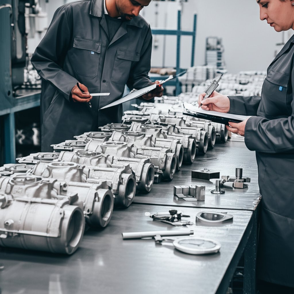
When you finally receive your prototype aluminium casting, how do you know it meets your expectations? The answer is a disciplined inspection process—one that catches issues early and keeps your project on track. Imagine having a casting inspection checklist that covers all the essentials, from the first look to advanced non-destructive testing (NDT). Here’s what to include in your RFQ and incoming inspection plan:
- Visual inspection: Scan for surface flaws—cracks, porosity, cold shuts, misruns, or discoloration. Use a magnifier if needed.
- Dimensional inspection: Measure wall thickness, hole diameters, and critical dimensions using calipers, CMM, or test rods.
- Material certification: Request chemical composition analysis to verify alloy and impurity levels.
- Metallographic examination: For critical parts, check internal structure for cracks, inclusions, or porosity using microscopy.
- Pressure/leak test: For components that must be airtight, use immersion or pressure testing to spot leaks.
- Non-destructive testing (NDT): Specify X-ray radiography, ultrasonic inspection, or dye penetrant testing to detect hidden defects.
By addressing these steps up front in your RFQ, you set clear expectations and avoid surprises when parts arrive.
Common casting defects and countermeasures
Sounds overwhelming? It’s easier when you know what to look for—and how to prevent it next time. Here’s a quick-reference table mapping typical aluminum casting defects to proven prevention strategies:
| Defect | How to Spot | Primary Causes | Countermeasures |
|---|---|---|---|
| Shrinkage Porosity | Internal voids (X-ray, sectioning) | Thick sections cool unevenly | Uniform wall thickness, add risers, optimize gating |
| Gas Porosity | Small holes (visual, X-ray) | Trapped gas, moisture in mold, poor degassing | Preheat mold, degas melt, improve venting |
| Misruns | Incomplete fill (visual) | Low pouring temp, slow pour, complex geometry | Raise temperature, simplify mold, increase pour speed |
| Inclusions | Foreign material (X-ray, microscopy) | Dirty melt, poor filtration, sand/mold debris | Filter melt, clean molds, maintain process hygiene |
| Hot Tears | Cracks at corners (visual, dye penetrant) | Restricted contraction, sharp corners | Add fillets/radii, review mold design, select suitable alloy |
| Warpage | Distorted shape (dimensional check) | Uneven cooling, thin/thick transitions | Uniform sections, controlled cooling, straightening fixtures |
Documentation that accelerates acceptance
Ever had parts delayed because the paperwork was unclear? Imagine instead that every shipment arrives with the right certificates and test data—so you can accept or reject with confidence. Here’s what to specify:
- Material certificates (alloy, heat treat, impurity content)
- Dimensional inspection reports (CMM data, test rod checks)
- NDT results (X-ray images, dye penetrant photos, ultrasonic scans)
- Pressure/leak test results (if applicable)
- Sampling plan and acceptance criteria (per ISO/ASTM or Aluminum Association standards)
By aligning on acceptance criteria and documentation in your drawings or purchase order, you minimize rework cycles and help your team move quickly from prototype to pilot builds. Referencing standards like ASTM B26/B26M for castings and ISO 9001 for quality management can add further clarity and confidence to your process.
Key takeaway: Proactive inspection and clear documentation are your best tools for porosity control aluminum and risk reduction. The sooner you catch and address defects, the faster you’ll iterate toward a production-ready design.
With your inspection plan in place, you’re ready to evaluate prototyping partners who can deliver not just parts, but peace of mind. Next, we’ll show how to compare suppliers for capabilities, DFM support, and rapid turnaround.

How to Choose a Prototyping Partner
What to evaluate in a prototyping supplier
When you’re ready to turn your prototype aluminium casting design into reality, picking the right partner can make or break your timeline, budget, and quality. Sounds daunting? Imagine you’re weighing a shortlist of aluminum prototype supplier options—how do you know which one will deliver not just parts, but peace of mind? Here’s what to focus on:
- Technical Capabilities: Can they handle sand, die, and investment casting—and do they also offer CNC and hybrid flows for finishing?
- Material Breadth: Do they support the full range of aluminum alloys you might need (A356, 380, 6061, 7075, etc.)?
- DFM Casting Support: Will you get actionable feedback on your design for manufacturability (DFM) before committing to tooling?
- Certifications & Quality Controls: Look for ISO 9001 or industry-specific credentials, plus robust inspection and documentation practices.
- Responsiveness & Communication: Are they quick to respond, transparent about lead times, and able to provide real design guidance?
- Scalability: Can they scale from a handful of prototypes to pilot or bridge production as your needs grow?
- Reputation: Check references and reviews—did previous customers get parts on time and to spec?
Comparing capabilities and turnaround
Not all rapid prototyping services are created equal. Some excel at quick-turn CNC or 3D printing, but may lack deep casting expertise. Others are die casting specialists, but slow to iterate or limited in alloy choice. To help you compare, here’s a practical table highlighting the key differences among leading providers—including a multi-process solution that stands out for cast prototype work:
| Provider | Core Capabilities | Aluminum Alloy Range | DFM Casting Support | Certifications | Typical Lead Time | Quality Controls | Best For |
|---|---|---|---|---|---|---|---|
| Rapid Prototyping Services | CNC, Injection Molding, Die Casting (metal & plastic) | 50+ materials, incl. 6061, 7075, A356, 380 | Yes – Complimentary engineering review for DFM | ISO 9001:2015 | Rapid (as fast as a few days for CNC, weeks for castings) | Full inspection, material certs, NDT on request | Multi-process projects, cast + CNC, DFM guidance |
| Protolabs | CNC, Injection Molding, 3D Printing | Variety (focus on 6061, 7075) | Limited—primarily for CNC and molding | ISO 9001, ITAR | Very rapid for CNC, moderate for molds | Standard inspection, traceability | Quick-turn CNC and molded prototypes |
| RapidDirect | CNC, Die Casting, Sheet Metal, 3D Printing | Range incl. A380, 6061 | Yes – DFM for die casting | ISO 9001 | Fast for CNC, moderate for casting | Material certs, inspection reports | Die casting prototyping, DFM for casting |
| Xometry | CNC, 3D Printing, Injection Molding | Wide (focus on CNC alloys) | Limited—mainly for CNC | ISO 9001 | Fast for CNC, 2–3 weeks for molding | Inspection options, traceability | CNC and casting provider for fast iterations |
Design feedback that saves time and money
Why does DFM casting support matter? Imagine you submit your design for a die casting prototyping project and get back not just a quote, but a detailed review of draft angles, wall thickness, and gating suggestions—before you ever spend on tooling. Providers with deep DFM expertise can spot issues that could cause defects, delays, or cost overruns. They’ll help you:
- Optimize geometry for casting success and easier post-machining
- Choose the right alloy and process for your functional goals
- Anticipate potential defects and suggest preventive design tweaks
- Streamline transitions between casting and CNC for hybrid parts
Key Takeaway: The best prototyping partners combine technical depth, rapid turnaround, and actionable DFM casting support—helping you iterate faster and avoid costly surprises.
As you evaluate your shortlist, prioritize suppliers who can pivot between casting and CNC as your design matures, and who offer transparent communication and robust inspection. Next, you’ll get a step-by-step action plan to move from learning to execution—so you can lock specs, submit RFQs, and launch your prototype aluminium casting project with confidence.
Next Steps for Your Prototype Aluminum Casting
Your action plan for the first prototype
Ready to move from research to results? Imagine you’ve mapped out your design, picked your process, and you’re eager to see your first prototype aluminum casting in hand. What’s next? Here’s a practical, step-by-step plan to keep you organized and on track:
- Finalize your alloy and process short-list. Use your functional goals and supplier input to select the right alloy and casting method for your prototype.
- Apply the DFM checklist. Review your design against best practices—double-check wall thickness, draft angles, fillets, and machining allowances using your DFM checklist casting (see previous sections for templates).
- Prepare as-cast and machining models. Clearly separate your as-cast vs machined model in your CAD files. Annotate or color-code faces and features that require post-cast machining.
- Paste your RFQ specification template. Use a standardized RFQ template casting (see earlier for examples) to ensure all requirements are clear and complete.
- Submit RFQs to two or three qualified suppliers. Share your full package—including CAD, drawings, quantities, and inspection needs—to get fast, apples-to-apples quotes.
- Confirm critical tolerances and finish specs. Before locking your drawings, validate any numeric tolerances or surface finish requirements with your supplier and reference materials. This step prevents costly surprises and ensures your prototype meets real-world needs (see IEN guidance).
Key Principle: Lock down your critical interfaces early—those features that must work with the rest of your assembly. Keep the rest flexible, so you can iterate quickly and cost-effectively as you learn from each prototype.
Lock specs, get quotes, and iterate fast
Sounds straightforward? It is, if you stay disciplined. The best teams don’t just send a model and hope for the best—they communicate context, clarify priorities, and invite supplier feedback early. This approach not only shortens your timeline but also builds trust and reduces the risk of costly rework .
If you need a multi-process partner that can handle both casting and CNC, or want complimentary DFM feedback before you commit, consider getting a fast, engineering-led quote from XTJ's Rapid Prototyping Services. Their team can help you bridge from concept to finished part with confidence, especially for projects that combine cast and machined features.
By following this action plan, you’ll move efficiently from concept to a quote-ready package—minimizing surprises and maximizing your project’s success. Now is the time to put your knowledge into action and bring your prototype aluminum casting to life.
Frequently Asked Questions About Prototype Aluminium Casting
1. What is prototype aluminium casting and when should it be used?
Prototype aluminium casting is the rapid creation of functional aluminum parts using temporary or soft tooling for design validation. It's best used when you need to test real-world geometry, internal features, or cast-like properties that machining or 3D printing can't replicate.
2. How do I choose between CNC machining and cast prototypes for my project?
Select cast prototypes when your design includes internal cavities, complex shapes, or requires cast microstructure. CNC machining is ideal for simple, external geometries or when fast, precise samples are needed without internal features.
3. Which casting process is most suitable for rapid prototyping?
Sand casting and rapid pattern methods are typically fastest for early-stage prototyping due to flexible tooling and quick turnaround. Investment and die casting offer finer detail but require more time and higher upfront tooling costs.
4. What factors impact the lead time and cost of prototype aluminium casting?
Lead time and cost are influenced by process selection, tooling approach, part complexity, alloy availability, secondary operations, and inspection requirements. Rapid tooling and clear RFQ packages help reduce both.
5. What should I include in my RFQ package for prototype aluminium casting?
A complete RFQ should have as-cast and machined CAD models, 2D drawings with tolerances, material and process specifications, desired quantities, inspection needs, and clear notes on critical features. This ensures accurate and timely supplier quotes.


